This thread has been locked.

If you have a related question, please click the "Ask a related question" button in the top right corner. The newly created question will be automatically linked to this question.

UCC23513: CMTI Test Circuit

Part Number: UCC23513

Hello team,

Customer would like to build up a CMTI test platform for UCC23513. We'd like to know below questions.

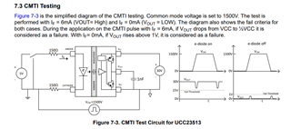
1. Could you offer the exact circuitry as what test platform you are doing?

2. Is output capacitor on Vout pin of the UCC23513 able to affect the output result? What R/C value is  suggested?

3. How about the Input resistor at Anode and Cathode pin suggested when doing the CMTI testing?

Regards

Brian

  • Hi Brian,

    The CMTI test bench we have uses a transmission line charged to 400V to provide a "pulse forming network". The edge rate is controlled by an RC filter. To get slower edge rates, we can use a GaN half bridge and change the Vbus voltage to get a specific edge rate.

    The output capacitor should float with the high side voltage, and should not play so much of a role.

    Currently I am trying to measure if there is a common mode current between the input and the output of one of our devices, and this seems to create a noisier measurement.

    The input resistor might affect input voltage when there are common mode currents. However, the usual source of failure is the capacitive isolation frequency, not the common mode current, so it would be surprising if different input resistors gave a completely different result.

    Best regards,

    Sean

  • 3. Update: I saw a lot of capacitive coupling between the output and the input during CMTI. This injected charge into the input. A falling edge was able to turn an IN=1 to 0, and a rising edge was able to drive IN=0 to IN=1.

    The solution was to improve the decoupling of the input. Added resistance is a bad idea, unless you can add a decoupling capacitor right at the input. 100pF was not enough, probably >=1nF is required. We eliminated the problem completely with a 220nF, but that was not an application level circuit, just a device characterization test.