This thread has been locked.

If you have a related question, please click the "Ask a related question" button in the top right corner. The newly created question will be automatically linked to this question.

TPSI3050-Q1: TPSI3050 output VDDM supply voltage level

Part Number: TPSI3050-Q1
Other Parts Discussed in Thread: TPSI3050, TPSI3052

Dear Experts,

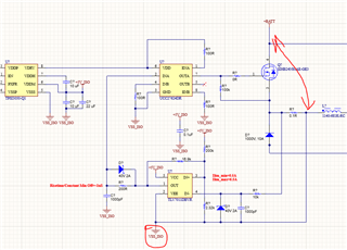
I would like to use TPSI3050's auxilary VDDM to supply an isolated amplifier.

The thing is that though that the minimum amplifier supply voltage is 4,5V and maximum 5,5V.

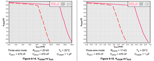
The VDDM as a supplier has a voltage minimum 4,6V which is quite close to the 4,5V threshold. I show here below:

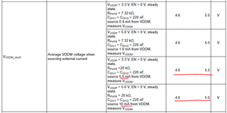
My load is between 5,5mA and 10mA but according to the above datasheet for both cases the VDDM is guaranteed from 4,6 to 5,5V.

The questions is how reliable and calculable the VDDM voltage and VDDM value depends on what exactly?

I am asking this because other than this range table I did not find any other indication of this in the datasheet and I have to guarantee that

the amplifier does not get a voltage out of the 4.5V and 5.5V range. Would you readily use this TPSI3050 supply for the amplifier in this case?

Thanks and regards,

Andras

  • Hi Andras,

    There are a few things that impact the VDDM voltage. The first would be the VDDP voltage that is being used to power the TPSI3050 device. The higher this is, the higher load you will be able to drive with the VDDM pin (and therefore will not cause the VDDM voltage to dip if you need to pull a higher loading). This can be seen from some of the application curves in the datasheet:

    Secondly, the amount of power transfer also influences how much current can be used to power other devices. By setting the power transfer setting to the maximum (RPXFR = 20k), you can allow for the highest possible current output and keep your output voltage within the range as shown in the datasheet.

    Lastly, temperature and process variation will have an impact on the exact output voltage from the VDDM pin. However, this is bounded in the datasheet (as you pointed out) to be between 4.6V and 5.5V. This means that we guarantee that all devices that we ship will have the VDDM voltage be between these two values across all temperatures, conditions, and process as defined in the datasheet.

    Let me know if this is clear!

    Thanks!

    Bryan

  • Dear Bryan,

    Thanks for your reply! I probably overlooked these charts in the datasheet, sorry about it.

    It is now clear that we can have about 10-12mA on the output of the VDDM.

    Two things I would like to further share with you and ask you opinion about:.

    1. I would like to implement the following a high voltage active precharge circuit

    and a high voltage voltage measurement circuit with an isolated amplifier.

    The precharge circuit (I calculated around 15mW for this circuit maximum from VDDH including the gate driver of course and comparator):

    https://www.ti.com/tool/TIDA-050063

    Plus I want the following isolation amplifier to be supplied still from VDDM (according to the datasheet 6mA is expected

    for VDD2 which is 5V*6mA=30mW total)

    https://www.analog.com/en/products/adum4195-1.html

    In theory with 15+30mW we should be fine with the TPSI3050's own power supply, what do you think?

    Honestly, I do not want to implement a discrete push-pull isolation transformer circuit if it is not necessary.

    2. In the charts that you attached above CDIV1 and CDIV2 has the same value though according to the following TI calculator

    CDIV2 has to be at least three times higher than CDIV1:

    https://www.ti.com/tool/download/SLVRBI9/01.00.00.0C

    What do you think about this? Also in the active precharge circuitry the ratio is more than 3:

    Thanks for you answer in advance!

    Regards,

    Andras

  • Hi Andras,

    Thanks for providing these additional details here. I do not see issue with you also trying to power an additional isolated amplifier from this VDDM rail, just make sure you are also taking into account changes in current draw at temperature as well (looks like the part you mentioned can draw up to 7.3mA at max temperature). Again, this is assuming we are operating with the maximum power transfer and 5V supply.

    So in regards to the different ratios you are noting, there is actually a subtle difference between the TPSI3050 and TPSI3052 as the TPSI3052 requires a different capacitance ratio (3:1) versus the TPSI3050 (1:1). This minimum ratio needs to be adhered to for each device in order for the device to be properly operated and maintain stability. In the design calculator you are using, make sure to select the correct part and that ratio should be adjusted to be either 1:1 or 3:1 in the tool.

    Thanks!

    Bryan

  • Hi Bryan,

    Thanks a lot, yes I overlooked this subtle difference. Probably it is because TPSI3052 has a +15V output for the gate drive.

    I'll consider all these when I finish my design!

    Thanks a lot and have a good weekend!

    Regards,

    Andras

  • Dear Bryan!

    Oh one more thing. I just found out a problem with this circuit. The ADUM4195 isolated opamp measures a HV DC voltage (+BAT)  rail with a resistor divider which  has to be referenced to the GND point (-BATT) of the HV DC rail so this means that the isolated opamp' power ground has to be the same as the -BATT. See the following:

    This means that I cannot use TPSI3050's auxiliary supply since its GND is referenced to the left side of the shunt resistor which is at the precharge circuit that is basically +BATT. I show this to you below:

    I was thinking about a solution how to solve it with one supply from TPSI3050 for example if I put the shunt to the negative side of the HV battery but this means that I have to pull in and pull out -BATT to and from the PCB via the 0.1mOhm and all the main currents (>50A) then would go through this resistor if I do not put switch also to the negative side.

    I think the most effective solution is to use another isolated supply only for the isolated opamp.

    What are your thoughts on that? Do you have something simpler solution in your mind?

    Thanks and Regards,

    Andras

  • Hi Andras,

    Hope you had a nice weekend! Yes, you are correct that you will need to keep those ground separated in order to have the right reference points for each set of measurements. I unfortunately do not have a more simplified solution to the one that you already mentioned which would be to use a different isolated supply with the reference to -BATT. Believe that would be your best option here!

    Let me know if there is anything else I can do to help!

    Thanks!

    Bryan