- Ask a related questionWhat is a related question?A related question is a question created from another question. When the related question is created, it will be automatically linked to the original question.
This thread has been locked.
If you have a related question, please click the "Ask a related question" button in the top right corner. The newly created question will be automatically linked to this question.
Hello,
I have configured the external circuit of controller to get the 90KHz at 45% duty PWM on primary outputs. Hence the RT ~82Kohm and external PWM applied across this resistor.
Test Condition#1: Running with circuit config: 90KHz and 45% duty.
Controller runs as expected at 90KHz and 45% duty cycle.
Test Condition#2: While running as above, external sync pwm (220KHz @ 50% duty cycle) is applied across RT resistor.
Controller gives the 110KHz PWM at output with 49% duty cycle.
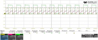
Test Condition #3: But as soon as you remove the sync PWM, controller is not going going back to PWM frequency set by resistor RT.
observed PWM frequency 38KHz at 19% duty cycle.
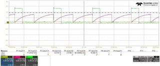
Why is controller not going back to PWM with frequency 90KHz when sync pwm is removed?
I can see peak voltage of RAMP is approximately 2.92V. In test case 1 &2, ramp peak voltage was 2.1V. why now ramp peak voltage has increased even though it is powered from Vref?
Schematic screen shot is as follows: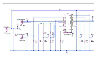
Hi,
How did you make the sync signal to RT pin? Can you show your circuit and signal on RT pin?
Hi,
Can you show the circuit? When you remove the SYNC signal, how did you remove?
PWM is generated by microcontroller pin, there is 50-ohm series resistor. it is directly driving the RT pin.
Note: it does have long twisted pair wire due to test setup limitations.
here is screenshot:
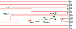
I wonder if microcontroller is pulling down its pin when we disable PWM.
Hi,
When you remove SYNC, is the 50-ohm to be grounded? Can you open the 50-ohm resistor manually to check?
I suspect the 50-ohm grounded so RT self setup resistor value actually becomes 50-ohm instead of the intended value for frequency setup.
How to interface the MCU PWM with controller then?
I tried a series high value of resistor so that it won't change the resultant resistance seen by Rt pin, but it's not working.
Hi,
One way is to use MCU I/O tristate pin, with high impedance if the MCU has tristate I/O pin.
Another way is to series a diode between the SYNC source and the RT pin so when disable SYNC, the I/O pin grounded while the diode block/isolate RT pin from GND through the diode.
A third way is to add a reverse connected diode to RT pin then use a capacitor to couple to your SYNC.
Usually one of the above should work.
Hi,
Please provide your circuit you tried and the associated waveforms to help find why no resolve the issue.
I tried later two things but still facing the same issue:
Option 1: diode in series
It syncs with PWM. when PWM is removed, it goes to 38KHz.
Option 2: capacitor in series with reverse connected diode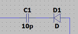
While syncing, I observed frequency variations in SYNC mode. when removed the sync, switching frequency went to 38KHz.
Hi,
Option 1, it may be due to the diode reverse leakage current. Can you first test without SYNC but with the diode reverse connected from RT pin to GND to see if you can set up fosc for the value not synched? This way can help adding the diode leakage current effect to the fosc setup.
What diode is used? Can you look for a diode with smaller leakage.
Option 2, C1 needs a discharge path. But since Option 1 works better, let's focus on Option 1.
Option 1:
When the following diode was connected antiparallel with RT, switching frequency is 92kHZ.
Diode: PMEG4010CEH
I will check for diode with smaller package aka leakage current.
Hi,
Previously, I was asking manually remove / open 50ohm resistor so disconnect from your MCU, to see if the fosc back to RT setup value. Did you try that? If ok fosc back to your RT setup fosc?
I tried that just now. I manually connected the PWM SYNC to the controller, then it gets sync to it. As soon as I removed the wire manually, PWM frequency goes to 38KHz.
Looks like controller does not allow these transitions from SYNC to RT resistor.
Hi,
Ok, that is what I thought.
The IC ok to work with that anti-paralleled diode on RT pin based on your test. Keep that diode in that way. The connect your SYNC to RT through a 100pF capacitor to see if the SYNC can be made. Then manually remove the SYNC from the 100pF capacitor to see if fosc back to RT fosc.
Note, the other end of 100pF still connected to RT pin when you remove SYNC or add SYNC so the SYNC is manually added or removed from the side of 100pF not connected to RT pin.
Hi,
While I am looking into any possible way to get it work, I think as you use MCU to make SYNC, and MCU I/O pin is always connected to RT. Is it possible you still use MCU to change the fosc to RT pin programmed fosc value instead of turn off SYNC?
let me look into that option more.
Here is more test results:
1. When controller is operating from RT resistor, Voltage at RT is 0.867 mV
2. When controller is operating from external clock. Mean voltage at RT is ~ 827mV
3. When external clock is removed this pin voltage stays at around 200mV.
Hi,
You may change to a new unit of UCC28251 to see if any difference.
Also consider if ok to use MCU to set up the fosc all time.
Hi,
I did some test. Basically I found my board with previously used for testing RT SYNC. It looks you need to use a 100k-ohm resistor to connect between RT pin and the SYNC source. My observation is ok to sync when connected and back to RT setup fosc after open the 100k-ohm.
I tried several different combinations of resistors including the 100 Kohm, it's not working for me. Please note that I am using UCC28251 instead of UCC28250.
Hi,
The SYNC function should be the same.
Can you provide some details what you see "not working" and show your RT pin waveform and SYNC waveform?
Not working as in: --> When the External sync PWM is removed then controller is operating at 38kHz.
I have following test results taken yesterday. I am still looking into this issue.
1. When running from the RT resistor: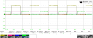
2. When running from external sync PWM: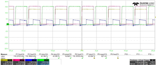
Note: I have level shifter connected at the output of controller to get the 15V PWM
CH1: One PWM output from Controller
CH2: PWM output after level shifter
CH3: RT Pin Voltage
CH4: Another PWM output after level shifter
3. When external sync is removed the mean voltage on CH3 is approx. 0.2V
Hi,
I assume no more support needed as no communication for a long time. I will close this thread. You can re-open this thread or create a new if needed.