This thread has been locked.

If you have a related question, please click the "Ask a related question" button in the top right corner. The newly created question will be automatically linked to this question.

LM5152-Q1: Load transient question

Part Number: LM5152-Q1

Hi Team,

My condition is Vin = 4.2V, Vout = 8.5V and load transient (0-10A)

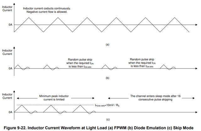
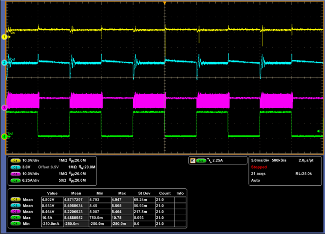
My CH3(pink) is SW node and I operate in FPWM mode. I'm not sure how to explain when no load. I expect that the SW should operate when no load. May you let me know your comment?

Regards,

Roy

  • Hi Roy,

    Thanks for reaching out. 

    At the turn-off instance, an overvoltage on the output is caused by the sudden change in the inductor current. I did some calculations and using your current compensation circuit, you have a phase margin of approximately 45 degrees, which is about the minimum required amount. If you would increase the phase margin a little bit, you could possibly decrease the oscillations that occur when the output current drops.

    An easy calculation tool to determine the phase margin and other parameters is the SLVRBL5 Calculation tool | TI.com. I'd also advise you to take a look at the necessary output capacitance given your desired system requirements.

    It seems to take about 5ms for the output voltage to drop back to 8.5V. I suspect that during these 5ms, where there is no load, the device is in skip mode, which is visible in the figure below:

    The switching then resumes when the output voltage reaches 8.5V. The skip mode should be visible if you keep keep the system in no load operation and you take some closer measurements.

    Thank you and best regards,

    Bryan

  • Hi Bryan,

    But I set as forced PWM mode by using mode pin. 

    Roy

  • Hi Roy,

    I'll get back to you tomorrow.

    Thank you and best regards,
    Bryan

  • Hi Roy,

    I've an explanation for this phenomenon, the LM5152-Q1 is a special kind of boost controller that's used for start-stop/backup battery systems.
    Therefore this component should only start switching when Vout is below a certain value.

    The behavior you're seeing is not skip mode, because like you said: you've configured the device to be in FPWM mode.

    Simply said: when the load step happens and the output current rises, the output voltage drops and the device starts switching. But as the next load step happens and the output current drops, the output voltage rises again and the device stops switching.

    If you would not have the load step that causes the output voltage to quickly drop, the output voltage would slowly keep dropping, and the device would resume switching once the output voltage drops below the regulation target VOUT-REG, which is programmable using the TRK pin.

    Thank you and best regards,
    Bryan