This thread has been locked.

If you have a related question, please click the "Ask a related question" button in the top right corner. The newly created question will be automatically linked to this question.

LM61460-Q1: EN/SYNC problem

Part Number: LM61460-Q1

Hi team,

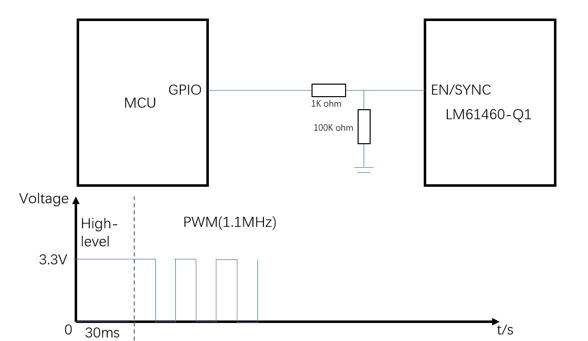
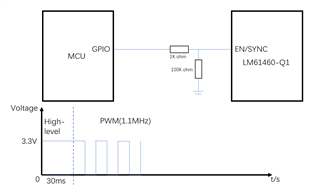
My customer do not want to use PFM mode in light load, they want to use FPWM. So they input PWM waveform at EN/SYNC pin when in light load.

They worry that this will cause abnormal situation, so they set the EN pin to high level for 30ms, then they change it to PWM. Is it ok?

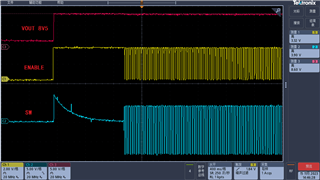
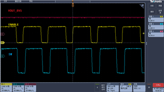
I put the real waveform below. Pls have a check.

VIN =12V VOUT =8.5V IOUT=50mA

Regards,

Peter

  • Hello Peter,

    Please refer to the Section 9.3.2 for EN/SYNC synchronization.

    The simplest way would be to have a RENT resistor pulled up to VIN so that EN is high and part is regulating to the resistor set by RT. Then an external clocking source is asserted onto the EN/SYNC pin through an AC coupling capacitor to switch the device from RT mode to synchronization mode. Note that it is recommended to do this synchronization after the device has gone through the proper start-up sequencing. 

    From there, after synchronization the device will be in FPWM mode. 

    Also if they needed a device that is always in FPWM, then they can pick the AFS variant which is always FPWM even during startup.

    Regards,

    Jimmy 

  • Hi Jimmy,

    I know the solution in datasheet. However, their project is in production status now, which means they cannot change the hardware anymore. They find that their load cannot run well under PFM mode. They want to fix the problem only by changing software. So they want to know if they can Input PWM like this.

    I will ask them to change the AFS device in the future board. 

    But for the board with AAS device, can they input the PWM waveform to run in FPWM mode? They do not want to change hardware.

    Regards,

    Peter

  • Hi Peter,

    Yes they can input a PWM waveform to run in FPWM, I don't see a problem with their current workaround solution.

    The real waveform you've previously provided shows the device regulating to the 8.5V output and the SW node appears to lock onto EN/SYNC external clock and switching in FPWM. 

    So long as the external clock is provided after the proper startup sequencing of this device in PFM, then the external clock will be able to synchronize the SW which is what I see in the waveform. 

    Regards,

    Jimmy