Hi,Experts
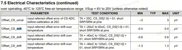
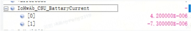
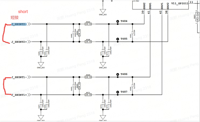
When using the BQ79731 for current sampling, after short-circuiting the connector, it was found that the sampling zero drift of shunt1 and shunt2 was very large. It was ±3uV (uncalibrated) in the specification. The measured chip pin difference was 0.8uV. The software read register was channel Channel 1 collected 4.2uV, and channel 2 collected -7.3uV. After replacing multiple samples, the data were basically consistent.
Please help me look at this issue. I have two questions:
1) Why does the zero drift exceed the sampling range? The software directly reads the register data without processing it;
2) Why does channel 2 have a different sign than channel 1? It is a negative value.