This thread has been locked.

If you have a related question, please click the "Ask a related question" button in the top right corner. The newly created question will be automatically linked to this question.

TPS25855-Q1: 15W USB-C charging issue

Part Number: TPS25855-Q1
Other Parts Discussed in Thread: TPS25854Q1EVM-164, TPS25854-Q1

Hello everyone, 

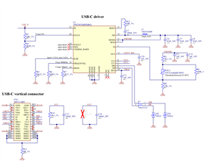
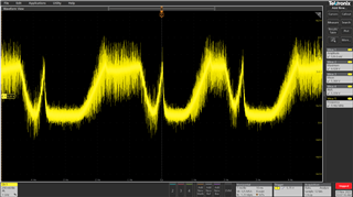
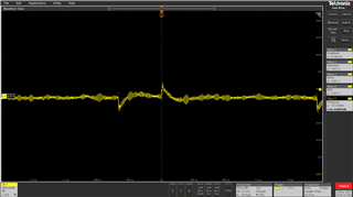
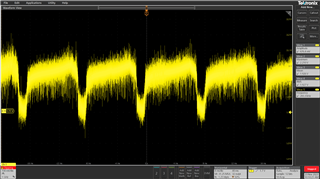
I'm trying to use the TPS25855-Q1 chip to produce a USB-C charging board with an output of 5V 3A but I have some problems with charging currents greater than 1.5A. The circuit I created is similar to the one proposed in the TPS25854Q1EVM-164 evaluation board. Using a phone with an almost empty battery starts fast charging but suddenly the input voltage drops from 24V to 8V and tries to keep the output current constant at around 1.25A  

I attached the schematic to this thread: in particular, for L1, I chose an inductance with 7A current saturation. The main voltage is 24Vdc and I limited the current of the power supply at 3A. I also tried with a USB-A tester with an adapter and it fails with 2A test current (the tester is Klein tools ET910). 
Could you help me with this issue, please? 

Thanks a lot!

Thomas

  • Hi Thomas,

    Shuai will help you on this case, thank you.

    Best Regards,

    Kuno

  • Hello Kuno,

    I need urgently support from your engineering application specialists due to an imminent spedition to our client (there is a large batch of devices involved).

    Best regards,

    Thomas

  • Hi Thomas,

    I will support you with this case.

    Based on the schematic there is a 3.3A current limit. But I'm a little confused with your description, what's the behavior for this issue? Is the phone can't be charged, or you mean the charged current changes due to something wrong? I don't understand why the power supply have a sudden change from 24V to 8V, you assume this is caused by TPS25855-Q1? Please help share more details information.

    Regards

    Shuai

  • Hi Shuai, 

    I'll explain better what I saw in the laboratory: by connecting a phone with a USB-C port the charger begins to deliver current up to a maximum of 5V 2A (10W). When it exceeds 2A at the output, the input voltage begins to drop from 24Vdc to 8Vdc causing instability in the switching circuit. To recover I necessarily have to disconnect the phone cable and reconnect it. 

    At the moment I have removed the current limit by bringing the ILIM pin directly to GND and increased the output voltage compensation to 300mV; furthermore I also added some 100nF bypass capacitors on the sense pin.

    I checked the thermal protection circuit and the voltage on TS pin never exceeds 2V during charging. The designed circuit is very similar to that of the evaluation board with the difference of the switching inductance: however I tested the circuit again with the 3.3uH inductance from Wurth and I didn't see any improvement. The layout of the board is based on the indications on the TPS25855-Q1 datasheet.

    I attach some screenshots acquired during the tests.

    This is sense pin during instability:

    This is CC1 voltage with no phone connected:

    This is CC1 voltage during instability:

    Thanks a lot Shuai!

    Thomas

  • Hi Thomas,

    Could you please help share the layout documents for further research.

    Best regards

    Shuai

  • PCB-2023-00402-01_USSC2601-prod.zip

    Hi Shuai,

    I've attached the gerber files of the card.

    Let me know,thanks.

    Thomas

  • I would add that I tested the board by removing the vias on the VBUS net and made the connection with an external cable.

  • Hi Thomas,

    Thanks for your update. And after the schematic review and test setup analysis I have several questions and advices, could you please help a try with it?

    1. There is a Rd resistor on CC1 pin, is it soldered on PCB board?

    2. Could you please help try with an electrical load to see if you can sink for 3A current? (With one Rd resistor connected on CC1 or CC2, then the VBUS output will be enabled.)

    3. Could you please help try with another power supply which have a higher current limit?

    4. From your test information, when you change the 3.3uH inductance, do you also change the FREQ/SYNC pin resistors?

    I will also try to find a EVM to see if I could duplicate this issue or try with a electrical load at least.

    Best regards

    Shuai

  • Hi Shuai, I'll reply following your order:

    1) Yes, R1 is soldered on PCB board

    2) Now I'm trying this test: is it necessary to add a pull-up resistor on CC1 pin to start 3A Current Advertisement?

    3) Yes, I tried but nothing changes

    4) No, I used 49,9Kohm resistor to configure 400KHz frequency switching with the 3.3uH inductance. Shall I have to raise it? On the evaluation board it is set at the same frequency...

    New question: Do I need to use a 100W USB-C cable to enable 3A fast charging or a active powered type-C cable?

    Best regards

    Thomas

  • Hi Thomas,

    I tested with TPS25854-Q1 EVM and used an electrical load to sink current from 1.5A to 3A. It turns ok with the charger.

    1) If you connect with a phone, then the Rd resistor is not necessary as the phone should integrated a Rd resistor inside.

    2) If you want to have a test with electrical load, then one Rd resistor is necessary to enable the VBUS output.

    4) I check the EVM and datasheet, 400KHz is OK with 3.3uH inductance.

    Usually a normal USB-C cable will support 3A current. If you have the 100W cable or better cable you could have a try, but I don't think it will have a influence for current issue.

    Best regards

    Shuai

  • Hello Shuai,

    I attached two images to analyze resistors configuration:

    So Rd is not necessary on PCB when I use a type-C cable with a phone, are you sure? 

    Thanks

    Thomas

  • Hi Thomas,

    Rd resistor should be integrated in Phone inside, source only charger will not provide a Rd resistor.

    Best regards

    Shuai

  • Thank you Shuai, with the electrical load I can sink current from 1.5A to 3A. 

    I noticed that there is a problem with the testing cable and phone.

    Thank you for the support!

    Best regards

    Thomas

  • OK, no problem, thanks for your update.

    Please go ahead and let me know if there are any further questions.

    Best regards

    Shuai Yuan