This thread has been locked.

If you have a related question, please click the "Ask a related question" button in the top right corner. The newly created question will be automatically linked to this question.

TLV62585: Inconsistent ripple voltage waveform in PSM

Genius 16395 points
Part Number: TLV62585
Other Parts Discussed in Thread: TPS62A01

Hi all

Please review below questions / schematic / scope shots from my customer and comment.

Best regards

Ueli

-------------------------------------

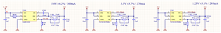
We use two cascaded TLV62585P to generate 3.3V and 1.2V. See attached schematic. The 3.3V buck converter runs in PSM. (Iout = 50mA) We have multiple prototypes with same PCB revision and same components mounted, but we observe inconsistent ripple voltage waveforms.

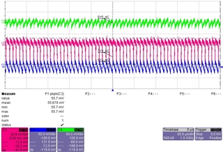
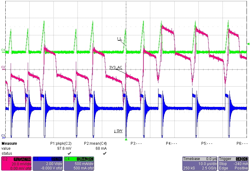
Approximately half of the prototypes show consistent ripple voltage, with 50mVpp. (See attached measurement, NormalRipple.jpg, red line)

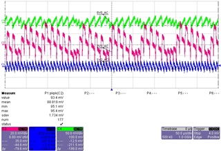
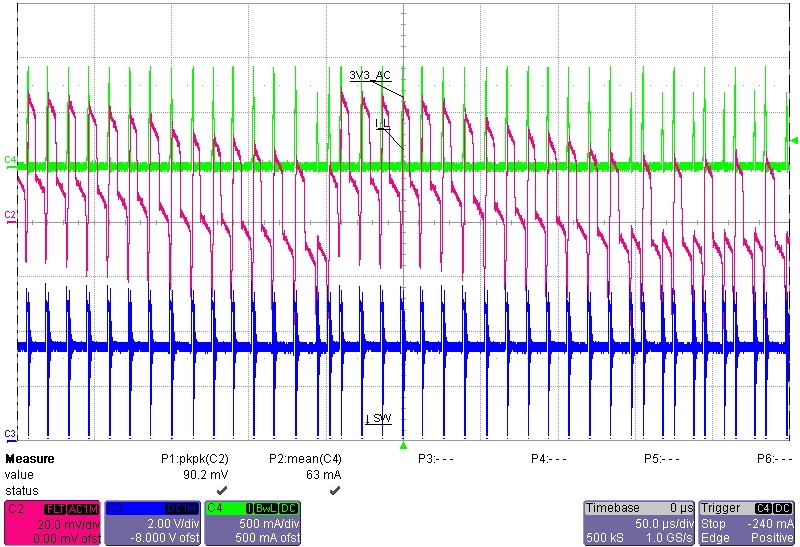
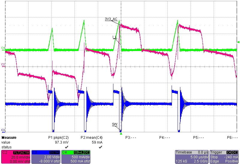
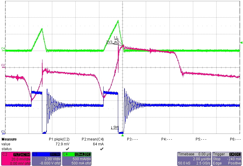
The other half shows inconsistent ripple voltage, with 100mVpp and very strange waveform. (See attached measurement, StrangeRipple.jpg, red line)

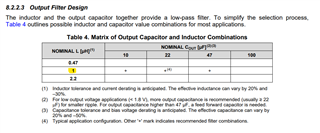
We've made measurements with various feed forward and output capacitor values. No significant improvement.

Any suggestions how to get a more consistent ripple voltage waveform?

Best regards,

Adrian

  • Hello Ueli,

    Thank you for reaching out, 

    Is the measurement setup same for both the waveforms shared?

    I would recommend to use tip & barrel method How to measure ripple for better design outcomes - Power management - Technical articles - TI E2E support forums for better accuracy.

    Did you tried to perform swap test?

    let me know your inputs.

    Thank you & regards,

    Moheddin.

  • Hi Moheddin

    Thanks for your reply.
    Measurement setup is the same for both waveforms. I've soldered very short wires to output capacitor C503. Oscilloscope probes are connected with small clamps. (Both GND and 3V3) Measurement loop is small. I've also tried the "pigtail" method mentioned in your link. Same result.

    I've swapped the TI TLV62585P from a "good" PCB to a "bad" PCB. The result is a mixture of the waveforms shared previously: The strange waveform is still there but occurs less frequent.

    I guess the varying behavior between different PCBs is caused by slight tolerances of the TI TLV62585P, tolerances of the surrounding components and slight variations in load current.

    Is there something we could change in the schematic to make the converter less prone to tolerances and get a more consistent behavior?

    (BTW: If I increase load on 3V3 by 5-7mA, all PCBs work fine. But that's obviously not an acceptable solution.)

    Best regards,
    Adrian

  • Quick update: I have mounted a TI TPS62A01DRL on the "bad" PCB. Now the ripple voltage looks fine.
    Maybe this information helps to find a more stable solution for the TLV62585P.

    (TPS62A01 is planned to be a second source.)

  • Hello Adrian

    Thank you for providing the information.

    What is the typical load current in which you observe this kind of Vout ripple?

    Did you tried to increase the load current and check the ripple?

    I guess it would be due the device is in transition phase from PFM to PWM. Can you please provide me the inductor current, SW voltage of 3.3V device at the point of this abnormal ripple behavior. Please plot Vout ripple, SW node voltage & inductor current in one, so that it will be easy for the analyses.

    Thank you & regards,

    Moheddin. 

  • Here are the plots you've requested:
    The first one has the same time base as the pictures provided previously. It shows that although we had to loop-in a current probe, behavior is still very similar to what we've seen before.

    All other plots show some situations with varied time base.

    Please let me know if you need more plots with other settings.

    Mean load current is approximately 50mA. Increasing the load by 5-7mA improves Vout ripple. But this is not really an acceptable solution Wink

  • Hello Adrian,

    Thank you for providing the requested plots. It looks like device is in PFM mode not in the transition phase. 

    I just looked your schematic and observed that you are using a 2.2uH inductor. But TI has evaluated and recommended 1uH inductor for this device.

    May be it's due to the stability issue, can you please try with the recommended value of inductor.


    Meanwhile can you also share me the layout file.

    Thank you & regards,

    Moheddin.

  • Hi Moheddin
    Thank you for the feedback.
    Because I don’t have a suitable 1.0uH inductor at hand, I soldered two 2.2uH inductors in parallel.
    Voltage ripple looks much better now and is more consistent for all tested PCB.
    I'll do a redesign, order the new components, and redo all of our verification measurements. I'm optimistic that your suggestion will do the trick.
    I think we can close this question for now. I'll report back in case the problem recurs.
    Thank you and best regards,
    Adrian

  • Hello Adrian,

    Good to hear. 

    If you don't have any further questions can you please close the thread by clicking on Resolved.

    Thank you & regards,

    Moheddin.