This thread has been locked.

If you have a related question, please click the "Ask a related question" button in the top right corner. The newly created question will be automatically linked to this question.

[FAQ] How to design the OVP resistor divider for TPS923655 / TPS923654 / TPS923653 / TPS923652?

Other Parts Discussed in Thread: TPS923652, TPS923653, TPS923654, TPS923655

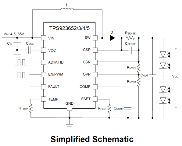
How to choose the value for the OVP resistor divider for TPS923655 / TPS923654 / TPS923653 / TPS923652?

  • Below are some guidelines on how to design the OVP resistor divider.

    1. The OVP pin of TPS923655 / TPS923654 / TPS923653 / TPS923652 has two thresholds,
      1. The first one is 1.1V. (Please refer to Section 8.3.6 and Figure 8-5 from the datasheet.) When the voltage of the OVP pin is below 1.1V, the output current won't be affected by the CV mode.
      2. The second one is 1.45V. (Please refer to Section 8.3.7 and Table 8-3 from the datasheet.) When the voltage of the OVP pin is above 1.45V, "LED open load" protection will be triggered.
    2. To make sure your output current won't be affected in all working condition, you should make sure Vout_max * R_OVP2 / (R_OVP1 + R_OVP2) < 1.1V. 
      1. Vout_max:
        1. If you are using the device in boost connection, then Vout_max refers to the sum of the maximum forward voltage of each LED in the LED string at your maximum target output current.
        2. If you are using the device in buck-boost connection, then Vout_max refers to the sum of the maximum forward voltage of each LED in the LED string at your maximum target output current plus your maximum input voltage.
      2. R_OVP1, R_OVP2: Please refer to the below figure.
    3. Please do not design R_OVP1 and R_OVP2 with too small values. Otherwise, there will be a severe leakage current path from Vin, the inductor, the Schottky diode, the sense resistor, the OVP resistor divider and then to GND. A too-small-value OVP resistor divider will also affect the output current accuracy as the resistor divider will shunt some current from the LED. A rule of thumb is that you can design the sum of R_OVP1 and R_OVP2 to be around 1Mohm or 2Mohm and this normally would be a good start point. You can then adjust the values based on your test results.