This thread has been locked.

If you have a related question, please click the "Ask a related question" button in the top right corner. The newly created question will be automatically linked to this question.

LMG3522R030-Q1: footprint related question NC1 and NC2 pins

Part Number: LMG3522R030-Q1
Other Parts Discussed in Thread: LMG3522EVM-042

Hello,

in datasheet it is mentioned on page 3.: "Used to anchor QFN package to PCB. Pins must be soldered to PCB landing pads. The PCB landing pads are non-solder mask defined pads and must not be physically connected to any other metal on the PCB. ..."

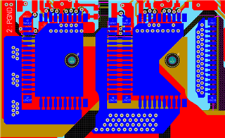
In documentation of eval board "LMG3525EVM-042" the pads are connected which is confusing.

What is the correct way to use the device?

Thanks & BR, Martin

  • Hi Martin, 

    The pads (1, 16, 17, 27, 43, 47, 52) are use to physically connect the device to the PCB. These pads should not be electrically connected to anywhere else on the board. Below is a screen capture of the EVM layout that shows these pads on the bottom layer of the board but not connected to any other nets on the PCB. The LMG3522EVM-042 Altium files are also available for download here.

    Best,

    Kyle Wolf

  • Thank you! I seem to have older design files where those pads are actually connected...