


Other Parts Discussed in Thread: TPS25750, BQ25798
Hi,
Before explaining the error situation, I would like to give some information about our circuit. Our ADCIN1 and ADCIN2 pins are supplied with 1.5V and cannot be changed due to the structure of the USB-PD-CHG-EVM-01 board, therefore it works in "AlwaysEnableSink" mode. We wrote the patch at EEPROM successfully.
We tried to read data from BQ25798 using the "I2Cr" command via TPS25750, but we were not successful. We wrote our data properly to the "slave address", "registeroffset" and "number of bytes" bytes in the DATA1 register. Then, we wrote the "I2Cr" command to the CMD1 register and when we read CMD1 again, we saw that the CMD1 register was 0. When we check DATA1 again, TaskResult byte 3 is "task rejected." We saw that it was. We encountered an interesting situation during our investigations with the oscilloscope.
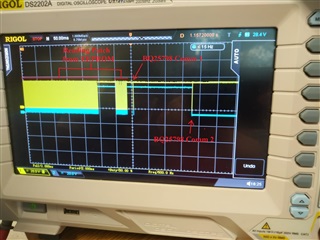
As you can see in the photo above, when we power the USB-PD-CHG-EVM-01 card, TPS25750 first reads the patch from the EEPROM. It then communicates with BQ25798. However, as can be seen, at the end of the communication, the TPS25750 keeps the clock line low. We examined the data between TPS25750 and BQ257598 with the oscilloscope, and I have presented this data to you in two parts below:
BQ25798 Comm 1:
110101100 000000010 000000110 010010000
110101100 000100000 100000000
110101100 000000110 000000000 110010000
110101100 000101000 000111000
110101100 000100010 000000000
110101100 000010000 000010100
110101100 000010010 000010100
BQ25798 Comm 2:
110101100 010010110 000000101
110101100 101110000 000000001
110010001
First, TPS25750 sends the data in "BQ25798 Comm 1" to BQ25798 and the line is normal(High) at the end of this communication. However, "BQ25798 Comm 2" in the second part sends register addresses that do not exist in BQ25798 twice and receives a NACK return. In the last packet, it sends the address "11001000", which is not the address of the devices on the line, and receives NACK immediately after the address. After this data, the Clock line remains constant at Low. For this reason, "I2Cr" and "I2Cw" commands cannot be used via TPS25750. Likewise, by connecting to the I2Cm line of the TPS25750, communication cannot be achieved with either the BQ25798 or the EEPROM.
While trying to solve the situation, we noticed that when we power the card only from the battery, the TPS25750 first communicates with the EEPROM again, but this time it only sends the data in the "BQ25798 Comm 1" section to the BQ25798 and does not send the data in the "BQ25798 Comm 2" section. Afterwards, we saw that the Clock line was in the High state as it should be. In this situation (with only the battery connected), when we connected the PD adapter, TPS25750 sent the data in "BQ25798 Comm 2" to BQ25798 and the Clock line fell back to Low state.
As a result, since the TPS25750 sends the data in "BQ25798 Comm 1" to the BQ25798, when we connect the PD adapter and the battery, we see the charging voltage and current values we set, but we cannot communicate with the BQ25798 or EEPROM. What could be causing this situation and what can we do to solve it?
Best regards
