This thread has been locked.

If you have a related question, please click the "Ask a related question" button in the top right corner. The newly created question will be automatically linked to this question.

BQ25180: No power in Vsys line

Part Number: BQ25180
Other Parts Discussed in Thread: BQ25181

Hello,

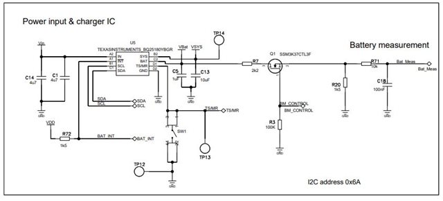
We are using BQ25180 battery charger IC in our customer design. We have encountered problems in production, as many boards do not function at all when boards are coming from assembly line. It seems that BQ25180 chips are not working as they should. When we connect a Battery (3.5 to 4.2V) to Battery pin or Power supply (5V) to Vin pin, some of the Charger ICs don’t give anything to the Vsys line. It seems that the Power Path from the inputs to Vsys output are in many cases completely turned off. Also, we can not communicate with the chips via I2C, as the chips do not respond to communication attempts. Please see the attached pdf for a little bit more detailed explanation with oscilloscope screenshots. 

We have checked the temperature profile of our assembly line and the paste we are using, and they should match the requirements for the components. We have X-rayed the solderings and we cannot find anything wrong with them either. Also, when we manually replace the faulty components with new ones, the boards start to work just fine. Also, we don't think this is a overcurrent situation, as we don't see any kind of hickups when power inputs are connected. In PDF a case with 150mA drawn from battery is shown and the output voltage rises to approximately 2 volts. We have no explanation for the 150mA current, and it is weird that some of the faulty BQ25180 will give some voltage to the Vsys line while others are completely dead.

Is BQ25180 component known to be very sensitive to assembly line conditions? It seems that there is almost identical component BQ20180 with a little bit lower charging current available. Could this BQ20180 be more "robust" in term of manufacturing (some improvements made perhaps)? You also have a BQ25181 in prototyping stage and in completely different package. Is this component coming to market soon and could it be easier to work with?

Sincerely,

Marko Ollikainen

BQ25180_Measurements_Feb17_2023.pdf

  • Hello Marko,

    Thanks for reaching out on E2E. Just a few questions to help in troubleshooting your issue. Would it be possible to send us a schematic?

    V/R

    Rafael Camarillo

  • Hi Rafael,

    Please see below the part of schematic with BQ25180 IC that I'm able to show. The Vsys line is connected to MCU and other electronics via power switch. This power switch limits the inrush currents required to charge capacitors (approx. 100 microfarads) to 500-600mA. Also, a Switch mode power supply is connected to Vsys, and when this SMPS is activated, the overall current drawn through the BQ25180 is in the 1000-1200mA range for a few microseconds, but this does not seem to cause any overcurrent problems with functional BQ25180 ICs, at least we have not observed any hiccups with the components. The I2C lines have 10kohm pull-ups and and seem to work just fine at 100kHz. The Battery measurement section does not load the battery/system very much as the resistors are in a kilo-ohm range. Also, our battery has a 10kohm NTC connected to TS/MR pin.

    Please let me know if you can spot something alarming in the schematic.

    Cheers,

    Marko

  • Hey Marko,

    Thanks for that.

    I do not see anything alarming with your schematic. Is there a way for you to test one of the IC's that is having issues by itself? Would it be possible to see if this IC would turn on a different board and get a couple waveforms? 

    V/R

    Rafael Camarillo

  • Hi Rafael,

    Thanks for checking the schematic. We have removed some bad components from boards and soldered test wires to pins in order to see if they could pass any currents from inputs to output. Unfortunately, we were not able to get any current from inputs to outputs. Also, we tried to activate them with push-button contact in a hope that the components might get out of some kind of unintended ship-mode state, but no luck with button either.

    We have had two or three components capable of passing current from 5V charger input to Vsys line, but once the charger was removed, the battery did not get connected to the Vsys and output collapsed. But by far the biggest problem is that no power from inputs is passed to Vsys line at all.

    We have also had couple of strange boards that worked when the battery input voltage was lowered below a certain limit (in a range of 3.0 - 3.5V), but when a higher voltage (3.5 - 4.2V) was applied to battery input, the chips refused to operate and no power to Vsys was passed through...

    We have manufactured a few hundred test boards so far, and have had several dozen boards with these strange problems. Practically every single board starts to operate once we manually change the Charger IC.

    Is there any preferred method for powering up the Charger IC? We are currently using Battery input as a primary source of energy in our board tester when waking up the boards and this seems to be fine for most of the boards, but should we try something else?

    Cheers,

    Marko