This thread has been locked.

If you have a related question, please click the "Ask a related question" button in the top right corner. The newly created question will be automatically linked to this question.

TPS25946: There are some problems in TPS25946 circuit measurement

Part Number: TPS25946
Other Parts Discussed in Thread: TPS62130A

Hi,

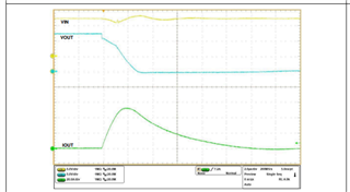
I have a customer who uses the TPS25946 with voltage fluctuations, resulting in voltage drops on the TPS62130A PG pin used later.

The details are in the attached document.

TPS25946_20231207.docx

Please help to see where the problem is,thank you!

  • Hi Rhea,

    It looks like the issue is due to high inrush current required by TPS62130A. Can you slow the startup for buck convertor by increase the cap at pin 9 (SS_TR) from 0.5nF to 5nF and test again to check if this resolves the issue. 

    Best Regards,

    Arush

  • Hi Arush,

    TPS25946 has done the following experiment, the effect is not obvious, please help to have a look, detailed description, please check the attached document.

    TPS25946_20231212.docx

    Many thanks~

  • Hi Rhea,

    In the document, I can see multiple values of SS was used to reduce the voltage fluctuations. Did they try changing SS_TR capacitor to around 5nF at TPS62130A pin 9? 

    Best Regards,

    Arush

  • Hi Arush,

    The SS pin welding 5nf and 15nf of TPS62130A has no significant change to the drop of VCC5V.

    No matter how the SS capacitor is adjusted, the voltage drop will occur when the load takes effect, so the measured modification of the SS pin capacitance does not have much impact.

    TPS25946_20231213.docx

    Thanks a lot~

  • Hi Rhea,

    I will check this and come back to you by Friday.

    Best Regards,

    Arush

  • Hi Rhea,

    I apologize for delay. Can you please perform the following tests. It will help in finding exact issue in the system.

    • Note: We need proper waveform with Vin, Vout and output current. In the oscilloscope, please add all these signals in same waveform and arrange them such that they don't overlap, and we can clearly observe the oscilloscope settings and signals. example waveform from datasheet is attached.
    • Test 1: Remove the R20 Net tie and test the Efuse alone to check the working of efuse alone.
    • Test 2: Now with dc-dc converter connected. You can solder some wire at the pads of R20 and use that wire to probe current. Provide all Vin, Vout and output current for efuse. Perform this for 2 values of SS_TR (pin 9) of TPS62130A. We will check the current signal for different soft start cap values for dc-dc converter.

    Test 1 will show if the device is fine or not and also will tell if the issue is caused due to high current required at startup of TPS62130A.

    Test 2 will help in correcting the issue if the issue is due to high current required at startup of TPS62130A. 

    Example image from datasheet (all signals in same capture and they are not overlapping) 

    Thank you for your patience,

    Arush

  • Hi Arush,

    Update the test as attached.

    Thank you for your support!

    TPS25946_20231219.docx

  • Hi Rhea,

    Looks like using 0.1uF for SS_TR is helping to reduce drop? 

    Regards

    Kunal Goel