This thread has been locked.

If you have a related question, please click the "Ask a related question" button in the top right corner. The newly created question will be automatically linked to this question.

LM5121: 12-24V to 50V@150W design verification

Part Number: LM5121
Other Parts Discussed in Thread: LM51551, LM5122, LM5123EVM-BST

Hello,

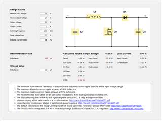
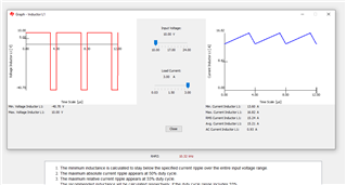
I've designed a DC-DC converter from 12-24V input (min. 10V, typ. 12V) to 50V output with 150W peak power. I did a simple Excel spreadsheet for simplyfying calculations, yellow cells are user inputs. Considering that converter will work in the range of 30-100W load for most time and 150W peak power will be used from time to time for a few minutes, are you able to check my calculations and schematics?

Thank you in advance.

Greetings,

Bart

lm5121_schematics.pdflm5121_calc.xlsx

  • Hello Bart,
    Thanks for reaching out to us via e2e.

    The schematic looks fundamentally o.k. But I did not yet have time to look at every component.

    Me can have a look at your calculations, but all members of our small team will be very busy until next Tuesday.
    So it would take some time to verify what you did.

    May I propose a different approach:
    Please download the Powerstage Designer tool from our website (you will need to go through a small Export Control verification).
    www.ti.com/.../POWERSTAGE-DESIGNER

    This is really a nice tool which will help you to calculate the external components for your power stage.
    Don't get confused by the picture for the Boost topology. It shows an asynchronas Boost, but it can also be used fo a synchronous version.

    I will get back to you in the first half of next week with more feedback on theschematic.
    Until then you can use the Power Stage Designer to help you with further calculations.

    Best regards
    Harry

  • Hello Bart, 

    One more question: 
    I just saw in a different thread that you had first tried the LM51551.

    May I ask why you have now chosen the LM5121? 
    Does this device have a particular feature that you need?

    To be honest, the LM5121/LM5122 are pretty old products, and the support is limited.
    May I propose that you have a look at the LM5123 instead?
    This part comes with a Quickstart Calculator tool which will help you a lot to design your application.

    At the moment, the Quickstart Calculator is hard to find.

    Please use the link that is given in section 9.2.2 in the datasheet:
    SLVRBJ1 Calculation tool | TI.com 

    Thanks and regards

    Harry

  • Hi Bart,

    Sorry for not hearing back for us until now.
    Could you tell me the current status of this thread?

    Are you still interested in the LM5122 device and need further review of your calculations, or could we convince you of the newer LM5123 device?

    Please let me know if you have any other open questions on these devices.

    Thanks and best regards,
    Niklas

  • Hi Niklas, Hi Harry,

    good to hear from you. I chose LM5122 due to my good experience with this chip. Good to know there is newer LM5123, it looks really good, however I cannot risk another failure, like with LM51551. Maybe I'll try it in future, but for now I would like to stick with LM5122.

    Greetings,

    Bart

  • Hi Bart,

    Thanks for the update.
    Then I will make a review of the LM5122 design you posted above and get back to you with my feedback by tomorrow.

    Thank you very much for your patience.
    Best regards,
    Niklas

  • Hi Bart,

    I had a look at your LM5152 schematic an the calculation sheet.
    I compared your results with our Power Stage Designer results. (This is the tool Harry recommended earlier in the thread)


    Calculations on duty cycle match with your calculations. The inductance of 10uH only matches if I set a inductor current ripple of 80%.
    Common ripple ratings are only around 30% to reduce inductor losses. This would then suggest an inductance of 26uH.
    The peak currents within the inductor don't match either.

    Here the tool sees worst case peak currents of 16.82A, so please make sure the inductor can support these current ratings.
    The tool also comes with a stability loop calculator to generate bode plots, which is very helpful for double checking the compensation.

    All other parts of the schematic look good to me.

    Best regards,
    Niklas

  • Hi Niklas,

    thank you for your feedback. I've designed two PCBs with LM5121, one of them is working well under 150W load, the second one fails to start even without load - I don't know what is the problem, but I decided to put it aside for a while and give LM5123 a try with another PCB design. Please keep this thread open for a while, I'll restart my tests after LM5123 startup and give back my feedback.

    Regards,

    Bart

  • Hi Bartosz,

    You should choose between the non-synchronous solution (LM51551) and synchronous solution (LM5121, LM5123) first.

    non-synchronous solution is simpler with lower efficiency.

    You should keep an eye on the SW voltage rating when using LM5123.

    Best Regards,

    Feng Ji

  • Hello again,

    I was testing both solutions with LM5121 and LM5123, the latter was promising, but as @Feng Ji pointed out, it stopped working at high load - probably due to higher voltage on SW pin than accepted by IC. LM5121 is the one I cannot tune to get it working, so I decided to change working conditions a little bit and stick to the datasheet only with my calculations.

    I have compared loop calculations with Power Designer and they seem to match quite well. The gain margin stays within -36 dB for 1A load and goes down to -19 dB for 4A load, where phase margin stays around 60 degrees for the whole time.

    Inductor I've chosen seems to be the highest current rated with the biggest inductance available off the shelf.

    Can you please take a look at the schematics and my calculations to verify if they are correct? I will attach PCB design later.

    Thanks in advance.

    Greetings,

    Bartosz

    lm5121_sch.pdf

    0825.lm5121_calc.xlsx

  • Hello Bartosz,

    I have just returned from vacation. I will look into it later today. 

    Best regards
    Harry

  • Hi Harry,

    thanks for the reply. As mentioned, I am attaching the PCB views (I don't know why there are no vias under components on top layer, but please ignore it, they are there).

    Regards,

    Bartosz

    lm5121_pcb.PDF

  • Hello Bartosz,

    Maybe I have overlooked this information somewhere earlier in this thread:

    Can you please let me know, why you are using the LM5121 and not the LM5122?

    Thanks and regards
    Harry

  • Hi Harry,

    just an old habit, I've used it once and it worked, so I decided to use it again. Are there significant differences between LM5121 and LM5122 besides lack of disconnect switch and freewheeling diode in LM5122 on the favor of clock sync? If the calculations may remain the same I can add a short on Q1 in current design to give LM5122 a try, but in the meantime, can you take a look at the schematics and PCB design?

    Thanks for your help.

    Regards,

    Bartosz

  • Hello Bartosz,

    I am sorry for the delay with the review.
    Both parts are fundamentally the same, except for the different feature set.
    As long as you can find a proper FET for the disconnect switch which can handle the required current in linear mode, everything is fine.

    Thanks and regards,
    Harry

  • Hi Harry,

    thanks for the reply, I've added three additional 0 ohm resistors which will allow me to replace LM5121 with LM5122. I will also order 22 uH inductor together with 15 uH to check the converter with 250 kHz switching frequency instead of 300 kHz.

    Have you had any chance to take a look at schematics, calculations and PCB design?

    Regards,

    Bartosz

  • Hello Bartosz,
    I want to apologize that I could not get to the review last week anymore.

    Here are my comments:

    Schematic and calculations:
    In the beginning of the thread, you had mentioned 150W.
    But the calculations are done for a 200W design.

    In case of 150W, the current sense resistor R2 should be set to 4 Milliohm.
    In this case, the current rating chosen inductor might just be acceptable.

    In case of 200W, the sense resistor value of 3 Milliohm is o.k.
    But the saturation current rating of the inductor will not be good enough.

    Please keep in mind that the calculated peak current is a theoretical number.
    It does not take into account any tolerances, losses, nor an additional margin to stay well below the saturation point.

    Regarding the inductance value, I would propose the following:
    If the input voltage is usually 12V and only reaches 26V in exceptional cases, you may want to choose an inductor with a smaller inductance value.
    Especially for a 200W system, where the input current is even higher, it may even go down to 5uH.

    I did not really calculate the compensation network.
    The HF capacitor seems to be quite big, I would usually expect values in a range below 1uF.
    The calculated values can anyway just be a starting point. Due to the influence of parasitic elements of the board, the proper values should be gained by experiments in the lab.

    Layout:
    I am not so happy with the placement of the ceramic input and output capacitors and the power ground concept.
    Please consider the current loops (including the GND return paths) on the input- and output-side.
    Those capacitors that are outside of the current flow (capacitors where the GND terminal is pointing to the edge of the board) are pretty much useless.
    Please try to place the power stage components, especially the GND pins of the ceramic capacitors and the source pin of the low side FET as close together as possible, like shown in our datasheets.
    See the GND pins marked in red in the attached image.
    You may also use the concept in the LM5123 datasheet as an example.

    Best regards
    Harry

  • Hi Harry,

    thank you very much for your input, appreciate it.

    I am aware that all of the calculations are purely theoretical - I've chosen the best inductor with acceptable Isat/price ratio, the converter will occasionally work under 160-180W load (and just for a few seconds), so I hope it will be ok.

    I've ordered the test PCBs and a bunch of components, I'll start testing next week and let you know the results right away.

    Best regards,

    Bartosz

  • Hello Bartosz,

    Even "just a few seconds" will be too long if the inductor goes into saturation and the current rises dramatically. 

    For a mass product I would definitely recommend leaving enough margin for all worst-case conditions (tolerances, temperature, etc..). 

    Best regards,
    Harry

  • Hi Harry,

    I get your point - few seconds in an electronics world is eternity. I need to test if my power receiver ever needs more than 150W, because those 160-180W are just hypothetical. My research shows it should need more or less 140W. If there is a bigger Isat inductor needed I can always use AGP42233-153ME (e.g. for mass production).

    Best regards,

    Bartosz

  • Hello Bartosz,

    O.k.  So, in your lab tests, please have an eye on the real inductor current under worst case situations.

    Best regards,

    Harry

  • Hi Harry,

    I've soldered one piece with LM5122 and already damaged 3 low-side transistors and I totally don't know why. My approach is to test converter without load first (only 10k resistor as standby load).

    After enabling power supply I saw output voltage rising to 50V but then it started to drop and my power supply switched to OCP. I was able to take a screenshot of output voltage and voltage at the gate of low-side transistor.

    1. Output voltage

    2. Output voltage zoomed

    3. Low side transistor gate zoomed (above zoomed section there is a preview of whole waveform)

    4. Low side transistor gate - time between switching

    Do you have any idea what is happening that the low side transistor is killed almost right after reaching output voltage?

    Best regards,

    Bartosz

  • Hello Bartosz,
    I am sorry to hear that you are having issues with your design.

    The FET can break because of an over-voltage (overshoots), an over-current (e.g. due to saturration of the inductor) or for thermal reasons.

    As a starting point I would propose adding gate resistors (maybe 5 Ohm) into the gate lines of b oth FETs.
    I would also ask you to lift the inductor on the input side. so that you can introduce a short cable loop. This will allow you to measure the inductor current with a current probe.

    Best regards
    Harry

  • Hi Harry,

    after more testing I thought about changing low side FET to a bigger one - it worked, so voltage overshoot seems to be quite possible - I will switch back to a default FET with additional Schottky diode between source and drain later on to check if it helps. I don't have a current probe for now but I will think about borrowing one when it is needed.

    No load conditions are tested, so I started testing the converter under load and here are the results:

    50 ohm load - ok, voltage output 50,9V

    100 ohm load - ok, voltage output 50,9V

    125 ohm load - not ok, voltage output 38,7V, audible switching noise

    My initial thought was to decrease switching frequency, so I replace R12 with 36,5kOhm resistor, effectively decreasing switching frequency from 300 kHz to around 246,5 kHz and here are the results:

    50 ohm load - ok, voltage output 50,9V

    100 ohm load - ok, voltage output 50,9V

    125 ohm load - not ok, voltage output 40V, audible switching noise

    There is a slight voltage increase at 125 ohm load between two versions and I have no clue where to look next for possible problems - increase Rslope? Change compensation circuit? Increase soft-start time?

    I'll be grateful for any hint.

    Best regards,

    Bartosz

  • Hi Bartosz,

    Please allow us some time to get back to you on this.

    Thank you

    BR,

    Haroon

  • Hi Haroon,

    I've made some progress and I should call it a milestone. I did what I wrote in the previous message - I've soldered two low side FETs in parallel with additional Schottky diode between source and drain and it is working perfectly (well, almost, but it is not instantly killing the FETs).

    This design is working quite well up to 150W but the transistors are extensively heating, I've stopped testing after reaching 90 Celsius degrees.

    I will order some heatsinks to test it further under 150, 175 and maybe 200W load.

    I'll keep you posted and won't hesitate to ask if any problem emerges.

    Best regards,

    Bartosz

  • Hello Bartosz,

    Good to hear that you are making progress.
    Please have a look at your Switch Node voltage.
    If there are big overshoots which have initially killed your FETs, you will need to reduce them.
    Too high positive and too big negative voltages can also damage the LM5121.

    Many people underestimate the importance of the layout.
    And - as I had stated before - your layout has a lot of room for improvement.
    You need to keep all power loops as small as possible.
    It is the enclosed area between forward path and reverse (GND) path that needs to be kept small.
    Also, the GND connections of the input- and output capacitors should come close together.
    Every additional millimeter of trace length will increase the parasitic inductances, which will cause the under- and overshoots.
    Especially at the power and voltage levels that you are dealing with.

    Burning these spikes (overshoots) in diodes or big FETs may be a workaround, but, as you just experience, the parts will heat up a lot.

    Best regards,
    Harry

  • Hi Harry,

    I get your point about parasitic inductances - after my tests I'll create another design and try to create as short current path as possible.

    I've also checked switching node under 50 ohm and 25 ohm load, voltage doesn't go below -3V and above 58,8V - undershoot worries me a bit, so a current path definitely needs to be improved.

    Speaking about layout improvement - do you consider LM5123EVM-BST board has a correct current path? This is something I can rely on while redesigning.

    Best regards,

    Bartosz

  • Hello Bartosz,

    The LM5123 EVM does not reflect the recommendation that is given in the datasheet.
    So, I would not recommend copying the layout / placement of the components from that EVM.
    At least you should move the sense resistor(s) and ceramic input capacitors away from the top and bring them to the left side of the inductor.
    Maybe also turn the inductor by 90° but keep the Switch Node small.

    Ultimately the distance between the GND terminals of the (ceramic) input capacitors, low side FET(s) and ceramic output capacitors should be as short as possible.
    Avoid surrounding the controller with the power stage components.
    Follow the written recommendations in these two datasheets (LM5123 and LM5121).

    Also, do not use thermal relief connections for the power stage components and the gate drive signals.
    I know that this will make the soldering more difficult, but solid connections are mandatory.

    Best regards,
    Harry

  • Hi Harry,

    thank you for all the hints, really appreciate that.

    Is there a chance I can share my design with you privately for a review?

    Best regards,

    Bartosz

  • Hi Bartosz,

    Please allow us some time to get back to you.

    Thank you

    BR,

    Haroon

  • Hello Bartosz,

    After accepting the friendship request, we should be able to exchange private messages.

    Best regards,
    Harry