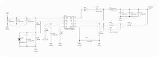
TPS62933P SCHEMATIC DESIGN IN THIS FILE
When VIN<20V , Vout =5.1V ,VIN>20V,IC Damage
How can I CHECK?

This thread has been locked.
If you have a related question, please click the "Ask a related question" button in the top right corner. The newly created question will be automatically linked to this question.
TPS62933P SCHEMATIC DESIGN IN THIS FILE
When VIN<20V , Vout =5.1V ,VIN>20V,IC Damage
How can I CHECK?

Hello William,
Thanks for reaching to us.
I don't think you should add the bead (60ohm?) between Analog_GND and Power_GND. That's not correct. Please remove it and use a short wire to connect.
Is your output 5.1V or 5V? The Rfb resistors are set to 5V, while you mentioned 5.1V.
The Pin7 is PG, not SS, so you can remove Css (C29).
You tied RT to GND, which set 1.2MHz fsw. So please follow our datasheet recommended LC table, using 3.3uH inductor.
