This thread has been locked.

If you have a related question, please click the "Ask a related question" button in the top right corner. The newly created question will be automatically linked to this question.

TPS74801-Q1: Power Limiting Mechanism and Thermal Protection Mechanism

Part Number: TPS74801-Q1
Other Parts Discussed in Thread: TPS74801

Hi Team,

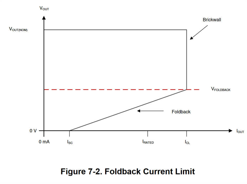
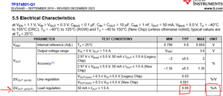
How much does the internal power limiting mechanism limit the power?

Our test found that after the output of TPS74801 was short-circuited to ground, it never turned off.

The specification describes that it will not shut down unless the Thermal shut down of the IC is triggered.

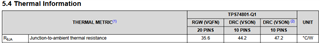
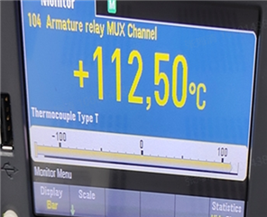
However, we kept short-circuiting the output to ground, and the IC did not trigger the OTP. We checked the temperature (IC TOP shell) and found that the IC has been at a temperature of about 112C. Here we are worried that the IC being at this high temperature will have an impact on the PCB board.

Thanks a lot.

Best Regards,

Matt.

  • Hi Matt,

    You are likely tripping the current limit in this case.  The current limit uses a foldback topology which lowers both the allowed current out of the LDO and it also lowers the output voltage at the same time (see figure 7-2 in the datasheet, also copied below).  Thus, while you are shorting the output you are not generating as much power dissipation as you might think.  If you wish to test thermal shutdown, load the LDO with 1.5A and raise Vin until the LDO begins to toggle on and off.  Thermal shutdown typically occurs at 165C for this device.

    You want to review the glass transition temperature (Tg) of your PCB.  Standard Tg is rated for 135C and high Tg is rated for 175C or higher.  As long as you are operating below the glass transition temperature, the FR4 will not begin to change its properties and your PCB should still be fine.  An LDO operating at 112C should not be hot enough to affect the PCB dielectric material.

    Thanks,

    Stephen

  • Hi Stephen,

    As you said, 

    "The current limit uses a foldback topology which lowers both the allowed current out of the LDO and it also lowers the output voltage at the same time (see figure 7-2 in the datasheet, also copied below).  "

    First, I cannot find the figure 7-2 in the datasheet. Could you please point out the figure in the datasheet from ti.com?

    Second, could you please tell me what is the power dissipation limit of the current * Voltage? As the output voltage will drop as the current reach the limit. 

    Thanks for your time and effort.

    Best Regards,

    Matt.

  • My apologies Matt, I must have copied information from the wrong datasheet by mistake.  There is no current foldback graph in the datasheet for this device.  Section 6.3.6 discusses the current limit but not the type.  This probably means brick wall current limit is used here, as I have seen this language used in other devices where brick wall current limit is used.

    The output voltage droop with increasing load current is called the load regulation in the datasheet.  Modern LDO's have very small load regulation values.

    The power dissipation limit of the LDO will depend on the thermal spreading of the PCB and the ambient temperature so it is not possible for me to tell you what the limit will be in every scenario.  For example, if your ambient temperature is 25C and the thermal resistance is 44.2 C/W (corresponding to the JEDEC standard measurement and the DRC package; see below) then in a typical use case you can dissipate over 3W.

    (165C - 25C) / (44.2 C/W) = 3.17 W

    The JEDEC standard is pessimistic in most cases and we typically see 25% - 50% reduction to these JEDEC numbers in actual board designs.  Thus, in a typical case you may see:

    (165C - 25C) / (44.2 C/W * 75%) = 4.22 W

    (165C - 25C) / (44.2 C/W * 50%) = 6.33 W

    Let's say your ambient temperature is now 70C and you have internal requirements to maintain a max junction temperature of 125C, but you still have a thermally saturated board design and your thermal resistance is 50% of the JEDEC value.  Then you dissipate 2.5W.

    (125C - 70C) / (44.2 C/W * 50%) = 2.5 W

    Thanks,

    Stephen