This thread has been locked.

If you have a related question, please click the "Ask a related question" button in the top right corner. The newly created question will be automatically linked to this question.

BQ76952: OCD1

Part Number: BQ76952

Hello, expert at TI!

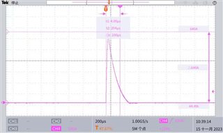
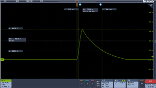
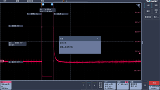
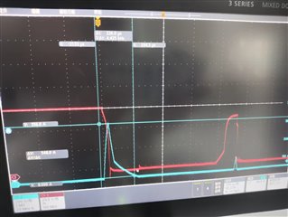
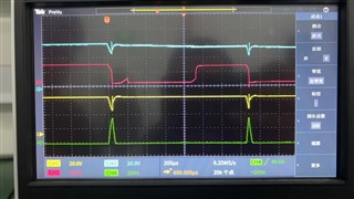
When I use bq76952, when my OCD1 delay is set to 300ms, that is, the value written by the register is 0x58, but the OCD1 delay waveform captured by the oscilloscope displays the actual time of 430ms. Other fault delay times are normal, such as OCD2, may I ask what causes this?

thanks.

  • Hello,

    I recommend taking a look at this previous thread, as it walks through some considerations for longer-than-expected OCD1 delays: (+) BQ76952: OCD1 Delay setting worsens OCD1 Threshold value - Power management forum - Power management - TI E2E support forums.  

    Additionally, if the command sequence window is reporting 0x58, then the decimal value is 88.  (88 * 3.3) + 6.6 = 297ms.  This means that the set delay is 297ms (This is very close to 300ms, but I just wanted to confirm).  I recommend taking a look at this FAQ as well: (+) [FAQ] BQ76952: How do I use Units and Native Units to calculate BQ769x2 register values in BQStudio? - Power management forum - Power management - TI E2E support forums.

    Best,

    Andria

  • Hi Andria,

    When I was testing SCD, a phenomenon occurred. My SCD_Delay was set to 400us, and the threshold was set to 200A. However, when I performed an external short circuit, the FET of BQ was turned off without reporting the fault. Of course, when I set SCD_Delay to 80us or below for external short-circuit test, a fault will be reported and FET will shut down, so I would like to ask what causes this?The following is the waveform of external short circuit when the SCD_Delay is set to 400US that I captured with the oscilloscope.

    I look forward to your reply. Thank you

  • Hello,

    Even though you are not seeing a fault reported, are you noticing an alert signal in the Safety Alert A Register when the short circuit event first occurs?  I believe the delay implemented may be too long for the SCD waveform being evaluated.  Can you provide the gg.csv file for the test where "the FET of BQ was turned off without reporting the fault," as I would like to look through other register settings?

    Please also see this thread: (+) [FAQ] BQ76952: What is the difference between OCD1, OCD2, OCD3 and SCD? - Power management forum - Power management - TI E2E support forums.

    Best,

    Andria

  • Hi Andria,

    Here are some of my register configuration values. When the short circuit in the above figure occurs, the alarm is not set.

    	ConfigData1.Power_ConfigL = Power_Cfg;		0x0068	
    	ConfigData1.Power_ConfigH = Power_Cfg >> 8;						
    	ConfigData1.REG12_Config = REG12_CFG;		0xDD	   
    	ConfigData1.REG0_Config = REG0_CFG;			0x01				
    	ConfigData1.HWD_REG_OPTION = HWDREGOPTION;	0x00		
    	
    	ConfigData2.Vcell_ModeL = gBq72Connect[0];		0xFFFF	
    	ConfigData2.Vcell_ModeH = gBq72Connect[0] >> 8;
    	ConfigData2.DA_Cfg = DA_CFG;      			0x02			
    	ConfigData2.CFETOFF_Pin_cfg = CFETOFF_cfg;		0x0000
    	ConfigData2.DFETOFF_Pin_cfg = DFETOFF_cfg;			
    	ConfigData2.TS1_cfg =TS1_CFG; 			0x07				
    	ConfigData2.TS2_cfg =TS2_CFG;			0x00						
    	ConfigData2.TS3_cfg =TS3_CFG;			0x00				
    	ConfigData2.HDQ_Pin_Cfg = HDQ_CFG;			0x00							
    	ConfigData2.DCHG_pin_Cfg = DCHG_CFG;		0x00
    	ConfigData2.DDHG_pin_Cfg = DDSG_CFG;		0x00
    	
    	ConfigData3.En_ProtA = EN_PRTA;			0xFC
    	ConfigData3.En_ProtB = EN_PRTB;			0xF7
    	ConfigData3.En_ProtC = EN_PRTC;			0xF6
    	ConfigData3.Prot_CfgL = PRT_CFG;			0x0002
    	ConfigData3.Prot_CfgH = PRT_CFG >> 8;
    	
    	ConfigData4.CHGFET_ProtA = EN_CHGFET_PRTA;		0x98			
    	ConfigData4.CHGFET_ProtB = EN_CHGFET_PRTB;		0xC4
    	ConfigData4.CHGFET_ProtC = EN_CHGFET_PRTC;		0x54
    	
    	ConfigData5.DSGFET_ProtA = EN_DSGFET_PRTA;		0xE4
    	ConfigData5.DSGFET_ProtB = EN_DSGFET_PRTB;		0xC4
    	ConfigData5.DSGFET_ProtC = EN_DSGFET_PRTC;		0xE0
    	
    	ConfigData7.Body_Diode_ThreshL = (u8)gBodyDiodePrt;		100
    	ConfigData7.Body_Diode_ThreshH = (u8)(gBodyDiodePrt >> 8);		
    	
    	BufSC = ((u16)gCurSCPrt * gCurSenseRes / 10);																	
    	ConfigData7.SCD_Thresh = GetSubscriptU16(BufSC, SCDThreshTable, 16);		400A		
    	ConfigData7.SCD_Delay = (gDlySCPrt / 15) + 1;				400us							
    	ConfigData8.SCD_Rec_Time = gTimeRecSCDHardPrt;			2s					
    
    	BufSC = (((u16)gCurHardDOCPrt1 >> 1) * gCurSenseRes / 10);			
    	ConfigData7.OCD1_Thresh = BufSC;					8A
    	ConfigData7.OCD1_Delay = (((u16)gDlyHardDOCPrt1 * 10) - 66) / 33;		300ms					//unit 3.3ms  excursion 6.6
    	
    	BufSC = ((gCurHardDOCPrt2 >> 1) * gCurSenseRes / 10);
    	ConfigData7.OCD2_Thresh = BufSC; 					80A
    	ConfigData7.OCD2_Delay = (((u16)gDlycurHardDOCPrt2 * 10) - 66) / 33;		300ms
    	
    	BufOCD = (-gCurHardDOCPrt3 / 10 * gCurSenseRes);			
    	ConfigData7.OCD3_ThreshL =  (u8)(BufOCD);				50A						// userA 10mA   
    	ConfigData7.OCD3_ThreshH =  (u8)((BufOCD) >> 8);			2s
    	ConfigData7.OCD3_Delay = gDlycurHardDOCPrt3;											//unit s
    
    	ConfigData7.OCDL_latch_Limit = OCDL_lATCH_LIMIT;			3		
    	ConfigData7.OCDL_Counter_Dec_Delay = OCDL_COUNT_DEC_DLY;		10
    	ConfigData8.OCDL_Rec_Time = OCDL_REC_TIME;				15
    	ConfigData8.OCDL_Rec_ThreshL = (u8)gStaticCurrent;			80mA
    	ConfigData8.OCDL_Rec_ThreshH = (u8)(gStaticCurrent >> 8);
    	
    	ConfigData8.SCDL_Latch_Limit = SCDL_lATCH_LIMIT;			3
    	ConfigData8.SCDL_Counter_Dec_Delay = SCDL_COUNT_DEC_DLY;		10
    	ConfigData8.SCDL_Rec_Time = SCDL_REC_TIME;				15
    	ConfigData8.SCDL_Rec_ThreshL = (u8)gStaticCurrent;			80mA
    	ConfigData8.SCDL_Rec_ThreshH = (u8)(gStaticCurrent >> 8);


  • Hi Zhang, 

    Just to clarify: you mentioned an alarm, but are you noticing an alert signal in the Safety Alert A Register?  Please see this FAQ for differences between the two: (+) [FAQ] BQ76952: Mask registers for Alarm Raw Status - Power management forum - Power management - TI E2E support forums.

    It makes sense that an SCD fault isn't triggering based on the delay set in the register. The oscilloscope waveform you sent does not have the SCD pulse remaining above the SCD threshold (400A) for the delay time (400us).  Please see this FAQ again: (+) [FAQ] BQ76952: What is the difference between OCD1, OCD2, OCD3 and SCD? - Power management forum - Power management - TI E2E support forums.

    I am a bit confused about why the FETs are turning OFF, however.  Are you noticing any other faults tripping during this time at could turn OFF the FETs, or do any other components in your system have the ability to toggle the FETs?

    Best,

    Andria

  • Hi Andria,

    I re-observed the alarm or protection situation when I was doing an external short circuit, and I found that the FET would not be turned off when the SCD protection bit was not set, and the SCD alarm was not set at this time. Moreover, I found a phenomenon that when my SCD_threshold was set to 200A, When the SCD_DELAY is set to 400us, the external short circuit occurs at this time, it will close the FET and SCD protection position at about 160us. The following oscilloscope waveform is recorded when I do the external short circuit.


    Please help me to see what causes it,

    thanks.

  • Hi Zhang,

    the FET would not be turned off when the SCD protection bit was not set, and the SCD alarm was not set at this time.

    This makes sense, as the BQ76952 must be configured for SCD protections in order to turn OFF the FETs during an SCD event.

    when my SCD_threshold was set to 200A, When the SCD_DELAY is set to 400us, the external short circuit occurs at this time, it will close the FET and SCD protection position at about 160us.

    This is odd--did the BQ76952 also trigger a fault along with turning OFF the FETs during this event?  Again, did any other faults occur that could have opened the FETs?  I want to make sure the SCD pulse is not causing another fault to trip and turn OFF the FETs before the SCD fault triggers.

    Best,

    Andria

  • Hi Andria,

    When SCD_DELAY is set to 400us, an external short circuit is performed, and then the SCD protects the position. What I want to know is why I set SCD_DELAY to 400us, but 165us protects the position during the short-circuit experiment. That seems like a big time difference.

  • Hi Zhang,

    I agree that this time difference is very odd.  Because you mentioned also not seeing an SCD fault triggering, only the FETs opening (which was assumed to be the SCD protection) in your earlier statement that "the FET of BQ was turned off without reporting the fault," I want to make sure the short circuit pulse didn't cause a different fault to trigger and open the FETs before the delay time of the SCD fault was reached.

    Since a short circuit condition is very stressful for a system, another fault with a shorter delay time could potentially be triggering, causing the FETs to close before the SCD fault can trigger.  Can you please confirm that there are no other alerts, alarms, or faults triggering when you are observing the behavior where the FETs are opening before the full SCD delay time?

    If you do not observe this, then I recommend setting the SCD delay for a shorter period of time so you will be able to consistently open the FETs at the desired delay time and observe the SCD fault being reported.

    Best,

    Andria

  • Hi Andria,

    If the SCD delay is too short, shutting down the FET may not be suitable for us. As you can see from the basic register configuration I sent you above, there is no fault whose delay time is less than or equal to SCD_Delay. And no fault was reported. This is the short-circuit waveform I made recently, including SRN, differential voltage of SRP, and waveform when there is no fault in the external short-circuit.

    This waveform is the differential voltage of SRN,SRP during an external short circuit.according to the SCD_Thresh 200A configured by me, the differential voltage of SRN and SRP should be 100mV, and the fault will occur when the time reaches 400us.

    This is the current at the same time and the waveform of DSG FET. The red one is DSG FET, and the light blue one is current.According to the above waveform, the condition of protection trigger is not met, but in fact, the DSG FET turns off synchronously when the current value rises, so I would like to know why the DSG FET turns off?

    thanks.

  • Hi Zhang,

    Since another protection is not causing the FET turn-off, the device may be performing an unorthodox type of resetting.  Do you have capacitors on the SRP and SRN lines?

    Best,

    Andria

  • Hi Andria,

    This is the waveform when I performed an external short circuit. Light blue is CHG FET, red is DSG FET, yellow is Vds, and green is current.

    This doesn't look like a reset.The following is part of our circuit schematic, please check if there is any problem.


    thanks.

  • Hi Zhang,

    I see that you have populated the capacitors between the SRP and SRN pins, but not the capacitors from the sense pins to GND.  Can you try re-running this test with these capacitors populated?

    Best,

    Andria