This thread has been locked.
If you have a related question, please click the "Ask a related question" button in the top right corner. The newly created question will be automatically linked to this question.
Hi,
I am trying to interface external Controller board to BQ76942EVM.
Below are the connectivity
1. Removed Jumpers J15 and J12
2. Connected SDA and SCL @J11 & J14
3. SDA and SCL are connected with Pull up of 10K to MCU 3.3V
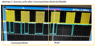
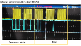
In controller, I have written code to read Temperature (TS1). I am reading 0xff. Same holds good for all other direct commands. Below is the scope capture.( Please note, I have not configured any registers. I assume, Direct read should give the values such as TS1 Temperature, Cell voltage)
Please let me know anything missing in my approach.
Sincerely,
Raj
Hi Raj,
The default register settings for the BQ76942 should configure TS1 for a thermistor, so this should be okay. There are many reasons why communication can fail, so I will include more information below:
I recommend connecting to the external MCU as described in Section 4.7 of the EVM User Guide: BQ76942EVM User's Guide (Rev. A) (ti.com). Using the MCU 3.3V is fine, and the pull-up voltage from the MCU would be connected at J11 and J14 (as mentioned above).
Just to get started, I recommend using BQStudio instead of an external MCU. Please see this FAQ: (6) [FAQ] BQ76952EVM: Why is my BQ769x2 device unable to connect with BQStudio? - Power management forum - Power management - TI E2E support forums.
A few follow-up questions:
Best,
Andria
Hi Andria,
Thank you for your prompt response and guidelines
1. I have tested the BQ76942EVM with BQtudio and after this I moved on to my external controller.
2. I have cross checked the connections and find it to be right as in 4.7 section of EVM user guide
3. I havent used the subcommand yet. Was trying to use direct command as shown in my oscilloscope capture.
4. External Pull up I am using 10K to 3.3V. Hope this is correct
Will keep you posted after few more testing.
Sincerely,
Raj
Hi Raj,
I am happy to hear that you were able to use BQStudio for preliminary evaluation. Since you were able to send commands successfully with BQStudio, the device is most likely not malfunctioning. A 10k pullup to 3.3V should not be an issue.
If you are concerned with the MCU's 3.3V supply, though, you can enable REG1 and use the on-board pullups. (see this thread: (5) BQ76952: BQ76952, How to get REG0 and REG1&2 enabled? - Power management forum - Power management - TI E2E support forums)
You mentioned shunt placement. Can you send a top-down, clear image of the entire board showing the connections?
Could you also respond to my last question?
Best,
Andria
Hi Andria,
Thank you for the response.
The I2C port connected to the BMS chip do not support clock stretching. Is there any work around for this!!
Sincerely,
Raj
Hi Raj,
Since the BQ76952 performs clock stretching, it is important to ensure the MCU you select also can perform clock stretching.
Clock stretching is when the peripheral device, in this case the BQ76952, holds the clock line low to indicate to the host controller that it is still processing the current command. Once it is done processing, it will release the clock to indicate to the host that it is ready to move on. The host controller's protocol would require reading the state of the clock line after releasing it to see if the clock is being stretched or not.
It is required to have an MCU that supports clock stretching when communicating with the BQ76952.
Best,
Andria
Hi Andria,
Thank you for your response.
We connected / hardwired the I2C to the same controller which supports Clock stretching. It is working.
Two straps on the custom board!! Since I was not aware of the Clock stretching requirement of BQ, I connected to the other I2C port(Which unfortunately did not had the clock stretching)
THANKS A TON FOR THE SUPPORT.
You can close the Ticket if you don't have any further suggestions.
Sincerely,
Raj