


This FAQ is to help explain why jitter exists in DCAP+ devices, when it is a problem, and how to minimize it.
Intro to COT control architectures
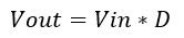
All buck converter control methods work by changing the duty cycle of the control FET to regulate output voltage. On average, excluding losses, the output voltage of a buck converter is as follows (D= duty cycle):
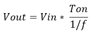
More traditional control architectures, such as voltage mode & peak current mode, work by increasing or decreasing the on time while keeping the frequency the same. This serves to increase or decrease the output voltage, or stabilize the output voltage in response to a load transient. Rewriting the equation above to break down D into its components, we get the equation below. This makes it clear how increasing Ton will proportionally increase output voltage in the ideal case.
COT (Constant On Time) control architectures, such as DCAP+, work by keeping Ton the same & changing the off time to achieve the desired output voltage. The effect can be seen by once again rewriting the first equation:
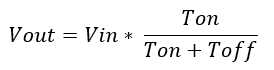
Because the on time does not change, and the off time does, the period & frequency must change to change the duty cycle. COT control architectures have the advantage of better transient response & easier tuning, at the cost of worse linearity & (usually) greater output ripple.
The important thing to note here is that frequency variation in response to a transient is not typical jitter – it is the intended regulation mechanism of COT (including DCAP+) devices.
Jitter in DCAP+
DCAP+ is a TI-proprietary control architecture for multiphase applications. Fundamentally, it is a constant on time, valley current mode control scheme, with some added features to make it particularly useful for multiphase power. A link to a useful app note on DCAP+ is here: https://www.ti.com/lit/an/slva867/slva867.pdf
Related to jitter, the most noteworthy observation is that a new pulse is triggered when the Isum_AC (summed instantaneous current of all phases) “touches” the Vcomp + Vramp signal. This is shown below:
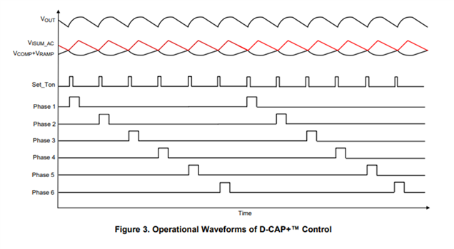
As a result, any noise in the ISUM signal will slightly delay or slightly advance the start of a new pulse. This is one of the forms of jitter frequently seen in DCAP+ designs. This becomes especially apparent with high phase count designs, as the ripple cancellation ensures there is relatively little ripple in the ISUM waveform to begin with. More detail on this effect is shown below (from page 5 of above app note):
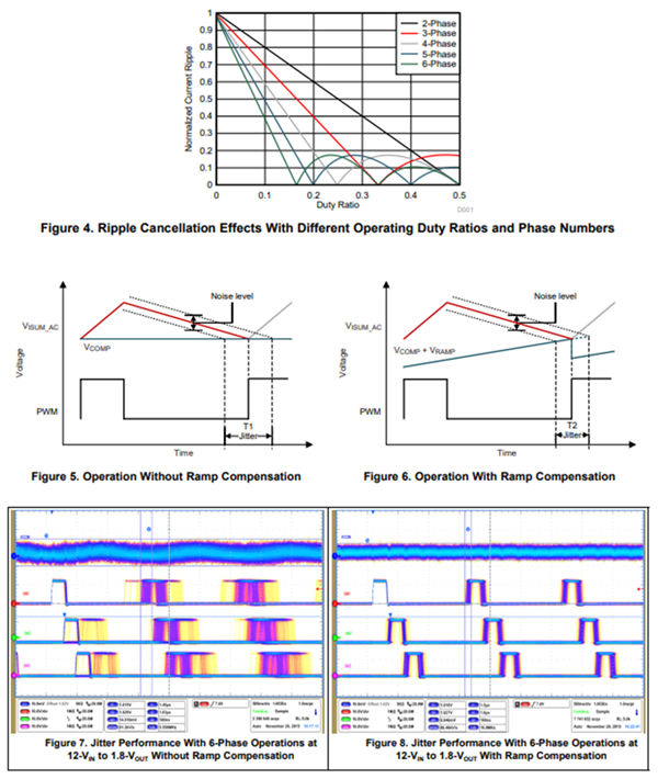
As seen in figure 6 & 8, increasing the ramp decreases the effect of ISUM noise on the start time of each pulse, decreasing jitter. For high phase count designs, we generally recommend starting with 440mV of ramp to minimize jitter. Higher ramp settings do decrease transient performance, so if the transient specs cannot be met with 440mV of ramp, then decreasing the ramp setting may be the best option. The ramp can be set in Fusion GUI, in the compensation section.
Jitter & Stability
Jitter in DCAP+ devices is not something that can be reduced to zero, and it doesn’t need to be. Having jitter in the 20-30% range is not unusual, particularly with a low ramp setting. As long as the transient response looks OK & there is no double pulsing, the jitter is generally not an issue from a stability perspective.
High jitter does increase output voltage ripple, which can be an issue for ripple-sensitive rails. In this case, increasing the ramp may be the best course of action. If the ramp is set to max & the jitter still cannot be managed, that implies different issue such as noise susceptibility or loop instability. If this is the case, more significant analysis is warranted.
Thanks,
Travis Williams
Applications Engineer, IPP-MPP