This thread has been locked.

If you have a related question, please click the "Ask a related question" button in the top right corner. The newly created question will be automatically linked to this question.

UCC2807-1: Some queries on 2807 datasheet

Part Number: UCC2807-1
Other Parts Discussed in Thread: UC2842, UCC28C42

Hi All!

I have a few queries regarding UCC2807 datasheet. 

1. The datasheet does not mention the delay between the detection of current limit (at CS pin) and reset of PWM signal. What is the delay for the UCC2807-1. 

2. In the datasheet in current sense section, there is a parameter COMP to CS Offset. Can you please help me to understand this parameter?

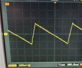
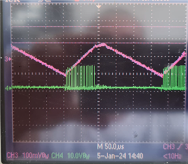
3. We are using UCC2807 to control forward converter in peak current mode control. At noload there the converter exhibit burst mode/cycle skipping operation. However, I want to know, how the control chip determines/calculates the upper and lower threshold of voltage to initiate/stop burst mode. 

Thank you!

Best Regards

Samir

  • Hi Samir,

    Answers to your queries below:

    1. The datasheet does not mention the delay between the detection of current limit (at CS pin) and reset of PWM signal. What is the delay for the UCC2807-1. 

    • Not a measured parameter for UCC2807 but if you take a look at similar general purpose PWMs such as UC2842 (Bipolar process) we specify CS to output delay as 150ns TYP and 300ns MAX and UCC28C42 (BiCMOS process, similar to UCC2807) as 25ns TYP and 70ns MAX. CS to output delay is the time from when CS reaches its threshold to the OUTPUT pulse turning off when falling to reach 90% of its high level. Your inquiry about CS to PWM Reset pulse delay is a subset of the delay time closely specified for UCC28C42 (70ns MAX) and the largest portion of that total delay time is propagation delay through the gate driver stage. 

    2. In the datasheet in current sense section, there is a parameter COMP to CS Offset. Can you please help me to understand this parameter?

    • COMP to CS offset is basically to specify the voltage drop from the diode shown at the error amp output (COMP), typically about 1.1V but can be close to 1.65V.

    3. We are using UCC2807 to control forward converter in peak current mode control. At no load there the converter exhibit burst mode/cycle skipping operation. However, I want to know, how the control chip determines/calculates the upper and lower threshold of voltage to initiate/stop burst mode. 

    • UCC2807 does not have burst mode/pulse skipping operation. A controller that has true pulse skipping would do something analogous to switching at a minimum duty cycle and then skipping every nth pulse. Some controllers even change to hysteretic mode to achieve pulse skipping. There are different ways to accomplish this but it's done intentionally and in a controlled manner so that the output stays in regulation. Pulse skipping will also impact output voltage ripple but again, this is done in a controlled and predictable manner. When the UCC2807 COMP voltage falls below the minimum threshold, pulses will stop until the COMP voltage returns. This is uncontrolled and somewhat random. Pulses are randomly appearing and then dropping out as opposed to periodically skipping.

    Regards,

    Steve

  • Hi Steven,

    Thank you for your kind response. 

    1.I am still confused about the time between current limit reached at CS terminal to PWM output from the chip turning off (excluding the gate driver portion). In the response above you have mentioned two different values for 2842 and 28C42. Which one should I consider. 

    3. I understood there is no pulse skipping operation embedded in UCC2807. For example, the output voltage at no load has ripple of around 200mVpp. The output voltage waveform looks as shown below

    During voltage ramp up, I can see most of the switching operation and during ramp down only few. Ramp up and down times are determined by the output caps but what determines the upper threshold and lower threshold seen in this voltage ripple. As you mentioned, COMP pin voltage which is a type of reflection of amount of current demanded from the converter determines this behaviour. Can you please further elaborate on this one.

    Thank you!

    Best Regards

  • Samir,

    UCC28C42 response time would be close to what you can expect for UCC2807-1. According to the measured output voltage ripple you are showing, the ΔV=500mVpp, not 200mVpp. The maximum peak ramping up is determined by ton and the minimum peak ramping down is determined by toff. The waveform looks to show an underdamped forward converter operating in CCM at/near the maximum input voltage. A simple tool for understanding the basic waveforms and operating modes (DCM vs CCM) is TI Power Stage Designer. Download and try it please? It is a free tool, easy to use and works with most mainstream power topologies and you can even model the control loop.

    Regards,

    Steve

  • Hi Steve,

    Thank you for your prompt response. So the delay tine for UCC2807-1 would be 70nS Max. Yes the ripple is around 500mVpp but just I wanted to show it as an example of output voltage waveform (shape) at no-load. Consider the output voltage waveform along with switching signals in below diagram.

    During the ramping up, there are we can see switching instances while ramping down no switching can be seen. I had taken this as burst mode operation, the switching action stops when the voltage reaches an upper threshold and initiates again when output voltage drops below some threshold. However I was curious to know what determines at which voltage level the switching burst stops and at which voltage the switching burst again starts. For example in above figure Voutnom+100mV the switching burst stops Sure I will use the TI Power Stage Designer to design the control parameters 

    Thank you!

    Best Regards

  • Switching start/stop is determined by FB/COMP/CS.

    Steve

  • Hi Steve!

    Thank you for your prompt response. What is the minimum threshold of COMP pin that causes the pulses to stop? I could not find information concerning this in the datasheet. And also can you please provide details about the voltage divider from COMP pin to the PWM comparator (shown in the functional block diagram)?

    Thank you!

    Best Regards

  • COMP min threshold is not a measured parameter and is therefore not specified in the data sheet. I can tell you the typical threshold is approximately 1.4V at 25°C but not guaranteed and variation process/tol/temp can be expected. Best recommendation I can offer would be to target pulling COMP below 0.5V.

    Steve