This thread has been locked.

If you have a related question, please click the "Ask a related question" button in the top right corner. The newly created question will be automatically linked to this question.

LP8764-Q1: does any change to stop the internal reset?

Part Number: LP8764-Q1

Hi 

We use the LP8764-Q1 on our automotive project.
the condition is:
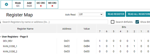
1. the RECOV_CNT_REG_2 (RECOV_CNT_THR) value is set to 0.
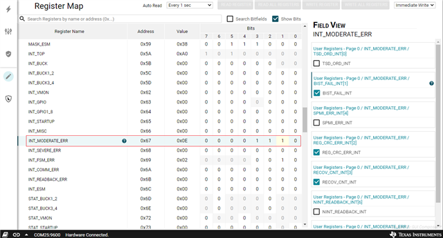
2. we turn the GENERAL_REG_1(REG_CRC_EN) to the "register CRC enable".

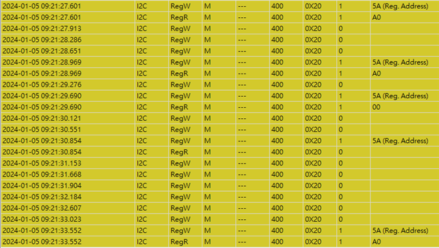
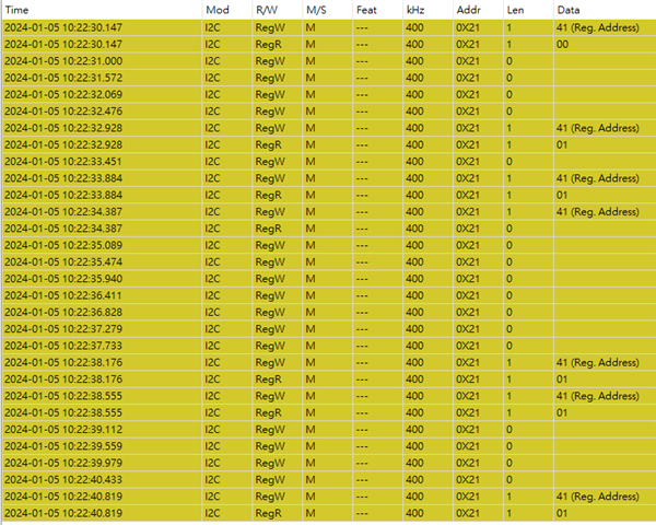
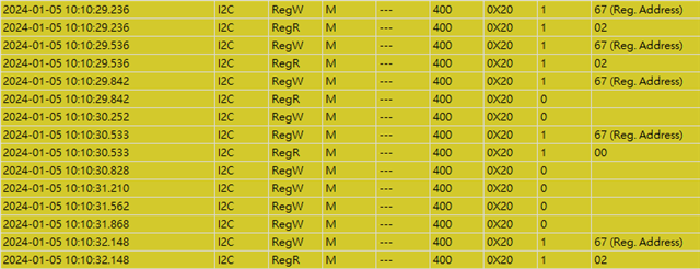
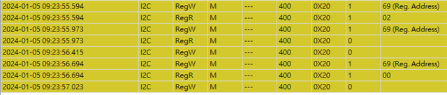
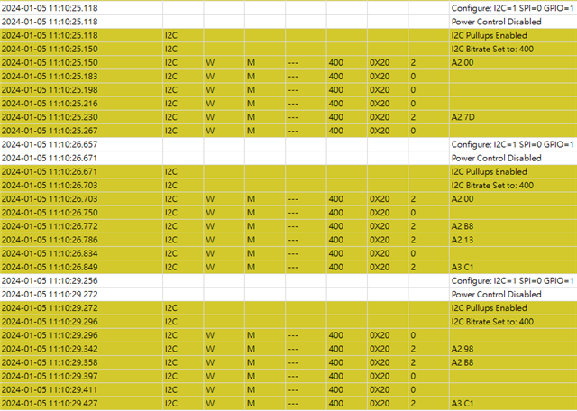
We use the Linux command to upgrade the PMIC firmware through the I2C interface. we do the power cycle after the program is finished, then try to do the CRC write. we found that the PMIC is not workable.

We know the procedure is incorrect, currently. the correct procedure should be the program the chip, then do the CRC, and the last step is the power cycle.

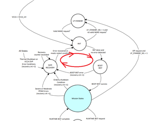
Is the PMIC working in the infinity initial loop state? do we have any way to stop it, and then use the Tool to access the chip?

Does the recovery count mean the RECOV_CNT_REG_2 register (RECOV_CNT_THR)?
If it is, we set the value to 0. seems the value 0 means no limit.
Is my understanding correct? do we have any way to change the stage to the SAFE RECOVERY stage?

Chris

  • Hi Chris,

    please expect a delay in response due to the Christmas holidays. Thank you for your patience.

    regards,

    Niko

  • Hello Chris,

    Could you please provide more information about your case ?

    What is the orderable part number for the device you are working with ?

    Are you working with an EVM ? Did you try to connect it to your PC and use the GUI meant for the EVM in order to inspect the device interrupts in the quick-start page ?

    Please have a look at Scalable PMIC NVM Update Guide (Rev. A) (ti.com) for more information on how to program the LP8764-Q1. There is a specific sequence to be executed which includes unlocking the NVM, disabling the PFSM and writing to specific pages / register addresses.

    Best regards,

    Florian

  • Hi Florian

    please refer to other cases.

    LP8764-Q1: error of "EEPROM Unlock Failed" when trying to reprogram an LP8764

    LP8764-Q1: REG_CR_EN = 1, but CRC value is wrong in the NVM. RECOV_CNT_THR =0. Is there a way to reprogram the device

    Basically, it asked the same question.

    we created an LP87641 code and turned on the CRC check.
    An engineer used the Linux script to do the FW upgrade but he didn't recalculate the CRC value and restore it before the power cycle.

    It causes the CRC detection error because the REG_CR_EN = 1 but the CRC value setting is empty.
    another problem is the RECOV_CNT_THR =0. Based on our measurement results before. RECOV_CNT_THR =0 means that the power will always retry while the power rail up is failed.

    the environment settings are not an issue on our side. we know how to use the tool and GUI. We can use the EVM and the GUI to access the good units.
    this issue happens on a few units because the upgraded processing is not following the guidelines. we try to solve/save those program defect units. in my opinion, if we can stop the retry procedure of the PMIC (LP87641), then we have a chance to access it and reprogram/upgrade the image.

    Chris

  • Hello Chris,

    Can you read the INT_TOP Register (0x5A) and subsequently the registers for which an error is reported ?

    Did you make the device configuration yourself ? If not, can you please provide the values for registers 0x01, 0x02 and 0x03 ? This will help us find more information about the configuration you are running and give more insight into how to recover the devices.

    Also, what value does 0x141 contain ?

    Best regards,

    Florian

  • Hi Floian,

    The TI dongle has some limitations to access the PMIC in this case.
    we used the AARDVARK I2C/SPI HOST ADAPTER to provide the I2C HOST and access the register of PMIC on the defect unit.

    we can not read the register 0x01, 0x02, and 0x03 on the defect unit through the TI GUI and tool. therefore we read it on the working unit.
    the register 0x01, 0x02, and 0x03 are :

    Working unit, Registe 0x01,0x02,0x03

    Here is the 0x5A result:

    Chip Address 0X20 Register 0X5A

    0X41 Value

    IC Address 0x20 Register 0x41 

    Here is more information about the 0x67 and 0x69

    Address 0x20 Register 0x67

    Address 0x20 Register 0x69

    On the other hand, please notice the time stamp. we tried to recover the configuration and send some commands into the chip.

    It seems that we cannot finish all command lines. the chip goes into reset/power down very quickly. 

    cannot send the full command into chip

    Chris

  • Hello Chris,

    Can you please confirm the CRC mismatch is the only difference between the working and non working devices ? The registers seem to indicate a BIST error provided the I2C readbacks are correct.

    Best regards,

    Florian

  • Hi Floian,

    Regarding your mention of the difference between the working and non-working device. the answer is "Yes and Correct".

    About it, I provided more information and description for you.
    ---------------------------------------------------------------------------------------------------------------
    we have to simulate the defect unit situation, therefore we clear the CRC register values to the 0(zero) on the workable unit.

    it is simulated that the Code / FW / Image upgraded but power cycle directly and forgot to calculate the CRC.

    the second part is the RECOV_CNT_REG_2 Register. the RECOV_CNT_REG_2 Register(0x84) value is 0.

    Currently, we know that the RECOV_CNT_REG_2 Register(0x84) is a key.
    if the 0x84 value is 0, the power can always provide a retry/detection of the power status.


    if we set the RECOV_CNT_REG_2 Register value to 1. the LP87641 PMIC will provide retrying /detection once feature. setting the value to more than 0 will decide the retry times.

    In our experiment, we set the value to 0. The unit seems no chance to access the end. It will be disconnected in the access procedure because the recovery processing has to read and write more than 5 bytes.

    we used another unit and set the RECOV_CNT_REG_2 Register(0x84) to 1. The PMIC will stop the internal program after the retry center is full. (retry once). then we can recover it back.

    that is why we would like to know, is it in the unlimited loop status as my picture in my first post?
    Do we have any chance to stop the loop or can access it again?

    Chris

  • Hi Floian,

    In addition, this picture shows that we set the RECOV_CNT_REG_2 Register(0x84) to 1 and it can stop the loop. we access the register 0x67 result after it stops.

    Set 0x84 to 1, read 0x67

    We can not access the defect unit (0x84 = 0) through the TI's tool/GUI because it will disconnect before we send the command.

    the AARDVARK I2C/SPI HOST ADAPTER seems more direct to access but still has some limits. (maybe the limit is caused by PMIC itself).

    Chris

  • Hi Chris,

    Yes, the register RECOV_CNT_REG_2 set to '0' means it will loop forever so this is not recommended option. 

    Also having incorrect CRC will cause this loop is not stopped ever. And there is no way to stop this. 

    Br, Jari