This thread has been locked.

If you have a related question, please click the "Ask a related question" button in the top right corner. The newly created question will be automatically linked to this question.

TPS61093-Q1: Voltage fluctuation

Part Number: TPS61093-Q1

Hi team, 

My customer acceptable for voltage fluctuation on TPS61093-Q1.

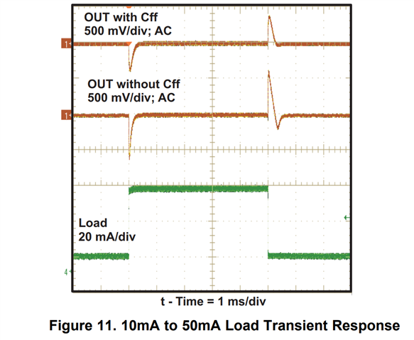
In datasheet, voltage changes nearly 500mV when load change.

Is there any way to suppress this fluctuation?

Regards,

Youhei MIYAOKA

  • Hi Youhei,

    Generally increasing the effective Cout can make this fluctuation (overshoot / undershoot) smaller.

    For further check, please send me the work conditions, such as Vin, Vout, Iout, Cout (capacitance and part number), the load transient range and the wanted fluctuation amplitude.

    Regards

    Lei


  • Hi Lei,

    Thanks. I'll check to the customer and feedback to you. It was a typo of "unacceptable". 

    Regards,

    Youhei MIYAOKA

  • Hi Youhei,

    Thank you. Let's further discuss later.

    Regards

    Lei

  • Hi Lei,

    They experiment at the EVM condition, they only changed FB resistor to change output voltage.

    Vin = 3.4V, Vout = 6.2V

    The customer does not want to drop below 6V at the 6.2V typ. voltage setting. The current change 50mA to 200mA.

    Could you teach me your recommendation please?

    Regards,

    Youhei MIYAOKA

  • Hi Youhei,

    Please advise customer to try the following ways:

    • Change the Cout from 1μ to 10μF or bigger, such as 22μF. Please note that the voltage rating of the Cout should be higher enough so it's effective capacitance doesn't degrade too much;
    • With above change, if the Vout drop has been below 200mV but the transient response is slow, then try to add a 22pF feedforward capacitor. On the EVM it's C6.  


    BTW, please also provide the feedback resistors used by customer. It's related with the more accurate feedforward capacitor calculation.

    Just let me know if the transient overshoot/undershoot is still not in the acceptable range with above modifications.

    Regards

    Lei

  • Hi Lei,

    Thank you for your prompt support.

    Sorry I couldn't understand your saying "Please note that the voltage rating of the Cout should be higher enough so it's effective capacitance doesn't degrade too much". Could you explain more detail please.

    Regards,

    Youhei MIYAOKA

  • Hi Youhei,

    For the widely used multilayer ceramic capacitor(MLCC), usually its effective capacitance decreases significantly as the DC bias voltage increases.

    Following is an example. The part number of the capacitor is CGA5L1X7R1H106K160AC, with the voltage rating 50V. You can see that when there is no DC bias, the initial capacitance is 10μF. When the DC bias is 25V, the effective capacitance is around 3.5μF only.

    Usually capacitors which in the same family will have bigger effective capacitance if the voltage rating is higher.    

    Go back to the customer's case, the needed effective capacitance is around 10μF. That's why I said when changing a 10μF or 22μF capacitor the voltage rating should be considered to guarantee enough effective capacitance.

    Regards

    Lei