This thread has been locked.

If you have a related question, please click the "Ask a related question" button in the top right corner. The newly created question will be automatically linked to this question.

UCC28C42: Stability problem

Part Number: UCC28C42
Other Parts Discussed in Thread: UCC28070

Hi,

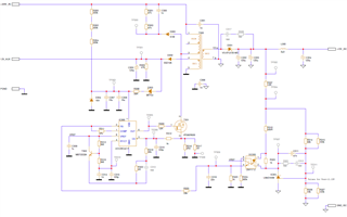
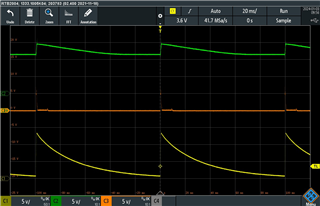
We are using UCC28C42 to generate an isolated 12V as well as a non-isolated auxiliary 12V. The input voltage is 400VDC (coming from a PFC stage), see the schematics below, the transformer is Wurth 750343306 with primary inductance of 360uH and turn ratio of 9.5:1. The design works as long as the AUX12V is connected only to the UCC28C42. As soon as a load of say 80mA (which is needed for other purposes) is connected to the AUX12V the device goes into hiccup. If we load the isolated 12V with say 40mA it will start working again but is seems awkward to burn half a watt just to keep things stable. I would appreciate any suggestion to improve this design.   

  • Hi Ramin,

    When you refer to "unstable", does this mean the output voltage is regulating but the OUT signal appears as missing pulses...or what you refer to as "hiccup"? 

    A controller that has true pulse skipping (hiccup) would do something analogous to switching at a minimum duty cycle and then skipping every nth pulse. Some controllers even change to hysteretic mode to achieve pulse skipping. There are different ways to accomplish this but it's done intentionally and in a controlled manner so that the output stays in regulation. Pulse skipping will also impact output voltage ripple but again, this is done in a controlled and predictable manner.

    When the UCC28C42 COMP voltage falls below the minimum threshold, pulses will stop until the COMP voltage returns. This is uncontrolled and somewhat random. Pulses are randomly missing as opposed to periodically skipping.

    If you need to add a min load to SEC2 (your regulated FB output) in order to maintain SEC1 in regulation, maybe check the cross regulation between these two outputs. The regulation of SEC1 depends on the regulation of SEC2 and the transformer coupling between these two windings. You can also check your power stage parameters using TI Power Stage Designer.

    Regards,

    Steve

  • Hi Steve,

    Thanks for answering so quickly, much appreciated. Here is what I mean by unstable:

    C1, yellow is the SEC1 (non-isolated, loaded by 80mA), C2, green is SEC2 (isolated and not loaded), C3, orange  is COMP (Pin 1)

    I am pretty new to this kind of power design and have inherited this design as is, so please bear with me. You mentioned “check the cross regulation between these two outputs” how exactly can it be done, could you please elaborate a little bit more? Also let me know whether any other signal could be of interest and I'll post it.   

     Regards/Ramin

  • Ramin,

    Cross regulation refers to the fact that only one output (SEC2) is regulated and the other output (SEC1) is cross regulated. The cross regulation of SEC1 depends upon the regulation of SEC2 and the transformer coupling between the SEC2 and SEC1 windings. Checking the cross regulation could mean verifying load conditions, as well as transformer coupling - how well are the SEC2 and SEC1 windings coupled together? Check with Wurth on this and see if the transformer has been constructed in a way to yield the most efficient coupling.

    Also, your waveform description indicates SEC1 (non-regulated winding) is loaded with 80mA but SEC2 (regulated winding) is unloaded. If this is truly how the converter is expected to operate, then you can expect start up problems such as what you are describing as "unstable." Normally the SEC1 winding is only providing bias power to the PWM (VDD) and this is <100μA start up and <3mA operating current. Loading the SEC1 with 80mA while the SEC2 is unloaded is not feasible and as you've already mentioned will require a dummy load to maintain regulation. Trying to start up the converter with such a loading mismatch will not be overcome, even if the transformer coupling between SEC2 and SEC1 were prefect. Maybe you could hold off whatever additional load is presented to the 12V_AUX, until +12V_ISO is regulating?

    Regards,

    Steve

  • Hi Steve,

    I was afraid of that. And for your knowledge it's not the normal operation condition i.e. unloaded ISO_12V but it could happen as the load is connected through a cable. Now this wouldn't be a problem normally even if the cable gets disconnected and AUX_12V goes instable but crucially in our case  the AUX_12V drives a PFC stage (also from TI: UCC28070 ) and much to our surprise this unstable AUX_12V results in uncontrolled (slow) voltage rise at the output of PFC. I've dared to measure up to 550VDC before disconnecting the input (set voltage is 400VDC). So it's really a safety issue.  I guss we just have to find other ways of dealing with this strange phenomenon.

    Thanks for your help

    Ramin