This thread has been locked.

If you have a related question, please click the "Ask a related question" button in the top right corner. The newly created question will be automatically linked to this question.

TPS2113A: VSNS minimum time for switching?

Part Number: TPS2113A

Hi~

IN1=MAIN POWER(OFF STATE, 0V), IN2=BATT connected.

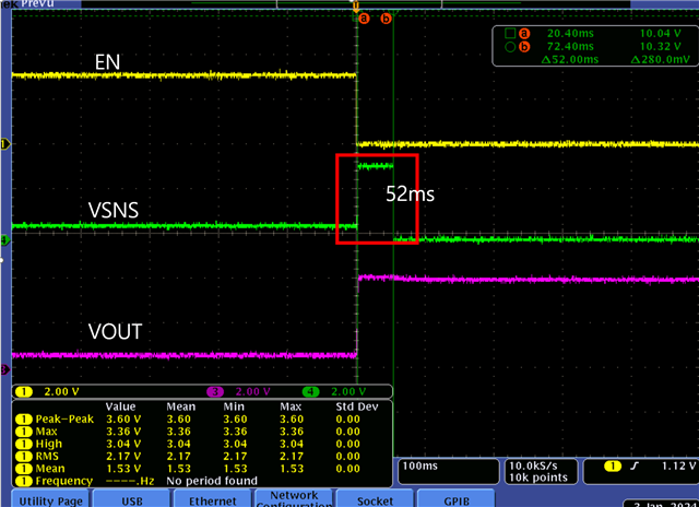
As shown in the picture, EN=LOW and VSNS=52ms high were applied.

VOUT does not become IN1(0V) even during VSNS=HIGH(52ms) and IN2(BATT)  is output.

It is confirmed that the output becomes 0V when VSNS=continuous HIGH.

What is the VSNS minimum time for VOUT to become IN1?

Best Regards.

  • Hi kwon,

    Please see note (2) of the page 7 Truth Table. If IN1 is selected while under 1.25V (falling), then the output will be Hi-Z. It looks like there is little current consumption during this 52ms timeframe, which is why the output voltage does not drop then, but it eventually falls to ground when the output stays Hi-Z.

    Is there something else driving the output?

    Thanks,

    Patrick

  • Hi Patrick,

    Looking at the VOUT waveform above, the starting voltage is 0V. After enable, the output voltage is maintained.

    It consists of TPS2113->BUCK-BOOSTER->LOAD(1A).

    If vsns is maintained, operation can be confirmed like a table.

    When VSNS has a puls width of 52m, the output is IN2.

    1. Is there a minimum maintenance time for VSNS?

    2. Should it operate like a table regardless of pulse width?

    3. Is there a possibility of this occurring if EN and VSNS are approved at the same time?

    4. When VSNS=N.C, about 1.6V voltage is generated. What is the reason?

    Best Regards.

    KWON.

  • Hi KWON,

    1. In the data sheet, the switchover looks to happen about 15us after VSNS is toggled. My thought is that what we are seeing is not because switchover is delayed with respect to VSNS.

    2. Yes, it should act according to the table as long as the pulse is greater than this ~15us. However, on the pin descriptions I see that an input can only be selected if it is above the UVLO threshold (1.25V falling, 1.3V rising). If VSNS > 0.8V and VIN1 < UVLO, OUT should be Hi-Z

    3. Yes, my thought to what's happening here is that there is a very short time between EN going low and the device seeing that VSNS is high where IN2 is connected to OUT, which creates the high voltage during the VSNS pulse. What interests me is that when the device switches back to IN2, VOUT drops a little bit. What is the load current during the VSNS pulse?

    Also, can you test the same scenario where EN going low and VSNS going high are separated by > 10ms (very large delay for definitive proof of idea)? This should help to answer our question.

    4. Perhaps what is happening is the device keeps switching between IN1 and IN2 when VSNS is floating because there is no defined level, and the device spends a significant percentage of time in switchover, which lowers the DC voltage.

    Thanks,

    Patrick

  • Hi Patrick,

    Thank you for your reply.

    3. The load current of IN1 or IN2 is the same(1A). The battery is connected to IN2, so the voltage drops little by little due to current consumption.

    Unfortunately, I can't do any more testing right now, so I'll do it next time. I will ask again about this issue during the next test.

    4. The last question wasn’t enough. Sorry~~.

    VSNS=1.6V occurs when VSNS=N.C.

    In FUNCTIONAL BLOCK DIAGRAM, it is comparator input port. I don't understand why VSNS=1.6V occurs.

    Thanks,

    KWON.

  • Hi KWON,

    3. Ok, understood - please let me know the result of the test when you can, hopefully it gives us a clear picture of the situation.

    4. Ah, my apologies as I misunderstood the question - we usually get questions about output behavior when an input is floating.

    Although I don't know for sure, my thought is that the VSNS comparator uses a BJT architecture, which would put the input/VSNS BJT base at the same voltage as that BJT emitter, which would be biased.

    Are you planning on VSNS being at times floating? If so, I would recommend putting a weak pullup/pulldown on it for redundancy.

    Thanks,

    Patrick

  • Thank you.

    Patrick.