This thread has been locked.

If you have a related question, please click the "Ask a related question" button in the top right corner. The newly created question will be automatically linked to this question.

Sync Buck Power Loss Calculation Tool (LM5148)

Other Parts Discussed in Thread: LM5148-Q1, SYNC-BUCK-FET-LOSS-CALC, LM5148

Hi all,

I have used the IC "LM5148-Q1" for the design of the buck converter, where I have calculated all the values according to the IC datasheet also verified with the support Excel file provided. Every thing looks good according to the calculation but I have an re-occurring issue that the converter output voltage is dipping with the addition of the load. the line regulation is fine i.e., at a fixed load the voltage variation is minimal but for different loads the output voltage is changing.

Here are my design considerations: 

Input Voltage range : 40V - 60V

Output Voltage : 13.8V

Output Current : 10A (Max load)

Switching Frequency : 500kHz to 600kHz

Inductor Current Ripple : 25% of Max output current

I am trying to find the losses at different load conditions but they are not matching the theoretical losses, so I went through the "SYNC-BUCK-FET-LOSS-CALC MOSFET power loss calculator for synchronous buck converter applications" Losses calculation Macro sheet. But I am not able to get the MOSFET selection correctly, even though I am choosing the voltage as 80V (input Voltage).

Input parameters: 

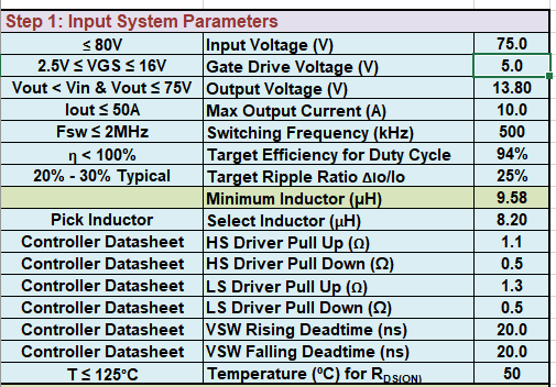
But the appropriate MOSFET selection is not available. Can you please guide through how to get the proper MOSFET selection.

Thanks

Mahankali Nikhilindu Kasyap

  • Mahankali,

    Not sure why the calculator is not working. Attach it and I can try to figure it out.

    It could be related to resulting FET temperatures, maybe try lowering current to see if it selects anything.

    Do you have more data or information on the LM5148 load regulation? 

    If it is small it could be related to resistive drops.

    If it is large it could be related to current limiting.

    When does it occur and what is the magnitude? A table would be nice.

    -Orlando

  • Hi Orlando,

    Please find the attached document of the Calculator with the inputs filled.

    As of the Load regulation I did solve it after adding the Gate Resistors, but my efficiency is not crossing 90% maximum, So when I was testing even further and observing the Wave forms there is slight Mis-match of the frequency( it might be because of the Resistor tolerance I thought). But the main parameter which is off from the MOSFET datasheet is the Rise time and fall time, which are the main cause for the high drop. So How to reduce these Parameters?

    Thank you,

    Mahankali Nikhilindu Kasyap

    SYNC-BUCK-FET-LOSS-CALC_Rev2.xlsm

  • Mahankali,

    It's strange that the gate resistor affects the load regulation that is not expected. 

    There might be some coupling from high-side gate to output, is HO routed close to FB?

    The SW node rise and fall time is dependent usually on high-side FET gate rise and fall time, which can reduce based on gate resistor.

    Also SW node snubber can reduce rise and fall time.

    Maybe check rise/fall time without snubber.

    -Orlando

  • Mahankali,

    I am closing this thread. If you need further assistance please start a new thread for further support.

    You can link to this by "Ask a related question"

    Thank you,

    Orlando.