This thread has been locked.

If you have a related question, please click the "Ask a related question" button in the top right corner. The newly created question will be automatically linked to this question.

UCC28C56H: Issue with Simulation

Part Number: UCC28C56H
Other Parts Discussed in Thread: UCC28C43, UCC28C52

Hello Team

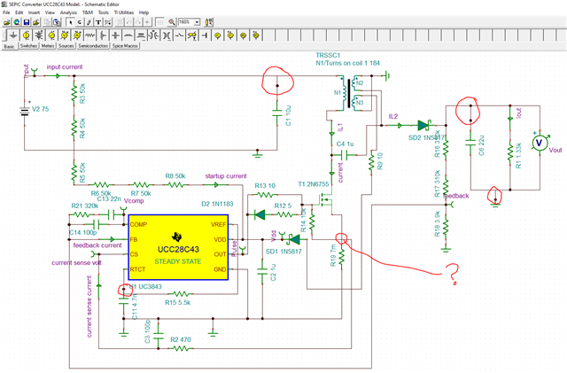
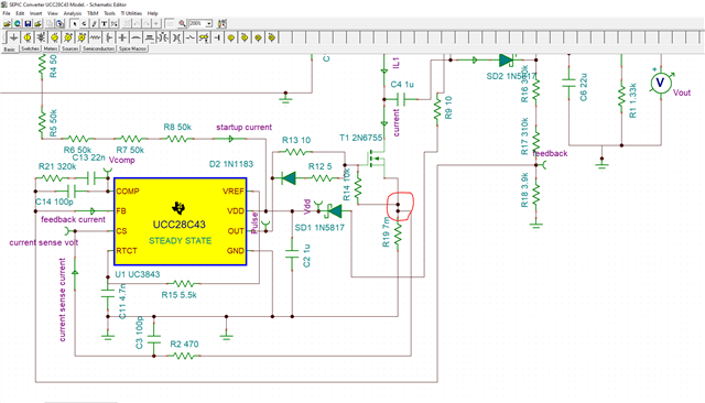
Attached is the simulation model of our SEPIC converter for wide input voltage. Facing issues with simulation. Kindly do the needful to proceed further.

Converter Specification:

SEPIC Converter

Input voltage range: 75V to 900V

Output Voltage range: 400V

Switching Frequency: 70kHz

Output Power: 120W.

Coupled inductor Lpri: 1.5mH Lsec : 1.5mH SEPIC Converter UCC28C56H Model..TSCSEPIC Converter UCC28C43 Model..TSC

Auxiliary winding to match required Vdd. 

Problem Statement:

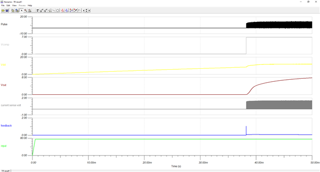
1. Ucc28c56H IC pulses are not coming properly. NO fixed frequency pulses are observed. Change in frequency and amplitude also observed at higher input voltage range. This observed when we fed voltage to Vdd pin through auxiliary as well as with external stable DC voltage supply.

Closed loop model is working from 150Vdc to 900Vdc input when the current sense limit is increased with UCC28c56H.

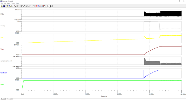
We also tried using UCC28c43 IC as well, but the pulses are not proper even with this model, but Closed loop model is working from 75Vdc to 900Vdc input when the current sense limit is increased with UCC28c43.

2. The currents measured at CS resistor is very high than beyond theory. CS resistor to be sized very small to measure higher currents then only the output is achieved or else if we size current sense resistor for calculated value it is not working.

In our case.,

Maximum primary peak current is 3A at 75Vdc. Adding some buffer, for 5A peak current if we select resistor for UCC28c56H 1V CS pin voltage, 200mOhm should be fine.

But were unable to get output. Primary current peaks are very high.

We used Nonlinear transformer part with separeted secondary coils to in place of coupled inductor to have auxiliary winding. As with coupled inductor we cannot model auxiliary winding.

Primary turns: 138T, Secondary 138T Auxiliary 37T.

3. Help in proper tuning of compensation if required.

Thanks

Vasu

  • Hi Vasu.

    I am taking care of this thread and I will reply back later today.

    Thank you

  • Vasu,

    Please check your schematic and correct errors circled below. Some are connected and the sim interprets them as such but others such as the CS signal are critical for proper operation and are not connected.

    Here I made one correction which was to connect the CS and you can now see the output is regulating to 400V as expected.

    The converter is still not stable and you can see this if you zoom into the output pulse (Pulse) waveform. Your compensation is not practical (single zero at origin, single pole at 5kHz). Fix the current loop first then stabilize the voltage loop. Use TI Power stage Designer loop calculator to help model the control then sim the component values inside TINA.

    Regards,

    Steve

  • steven,

    Thanks for the feedback. As suggested the 

    1.  Connection were redone yet observed the same waveforms and as per our calculation the peak current is 3A with additional buffer current sense resistor is selected as 200mohm for 5Apk current. With this Rcs value, Output is not reaching 400V in any of the input voltage condition.  But by reducing the Rcs value (to increase CS limit) we could able to achieve 400Vdc output. Not sure why the Primary peak current is going high ? Please help, Is their any problem here.
    2. TI power stage designer doesn't have SEPIC converter option in control loop design. Kindly help here for any alternate. 
    3. Presume Ucc28c43 and Ucc28c56H are same except some start up current improvement. Please confirm. As we are getting some better results with Ucc28c43 but we are planning to Ucc28c56H. Is this is going to resolve after proper compensation tuning.
    4. Hope for our application SEPIC is the good topology and UCC28c56H can be used for SEPIC.
  • Vasu,

    1. Connection were redone yet observed the same waveforms and as per our calculation the peak current is 3A with additional buffer current sense resistor is selected as 200mohm for 5Apk current. With this Rcs value, Output is not reaching 400V in any of the input voltage condition.  But by reducing the Rcs value (to increase CS limit) we could able to achieve 400Vdc output. Not sure why the Primary peak current is going high ? Please help, Is their any problem here.
      1. Think about the peak current in terms of the PWM controller sensed current. The sim I sent you shows the sensed current is below the threshold specified in the data sheet and as a result, the output voltage is regulating to 400V as expected. You transformer turns ratio is not correct. The turns for N3 supply bias to the PWM are too low to maintain VDD > UVLO_OFF. The turns for N2 are too high and this makes your peak primary current close to 15Apk instead of the desired 5Apk.
    2. TI power stage designer doesn't have SEPIC converter option in control loop design. Kindly help here for any alternate. 
      1. Correct
    3. Presume Ucc28c43 and Ucc28c56H are same except some start up current improvement. Please confirm. As we are getting some better results with Ucc28c43 but we are planning to Ucc28c56H. Is this is going to resolve after proper compensation tuning.
      1. Yes
    4. Hope for our application SEPIC is the good topology and UCC28c56H can be used for SEPIC.
      1. Yes, either controller can be used for SEPIC but why use UCC28C56H with such high UVLO? This controller is intended to drive SiC MOSFETs. Are you intending to be applying VGS~16V to a Si MOSFET? UCC28C52 seems to be the better choice.

    Attached is your UCC28C56 SEPIC TINA model - I made some mods to get it closer to what I believe you are trying to achieve but it still needs more work, particularly for the transformer, RCS and compensation.

    SEPIC Converter UCC28C56H Model_TI MOD_01082024..TSC

    Regards,

    Steve

  • open loop sepic(1.2m).TSC

    Hello Steven

    Have couple of queries inline to trailing conversations and expect your support in both the points below.

    1. We have simulated the SEPIC converter in open loop with TINA to see whether the peak current at L1 [coupled inductor primary] is still very high as in closed loop or not. Even with open loop simulation, we are facing very high peak currents at L1 primary at 900V input. We used Coupled inductor model.

    Attached is the simulation file please check once and let us know why the current at L1 is very high at 900V input. whereas at 75V input the current is around the expected value.

    Note: For Open loop simulations please consider Fsw = 70kHz and vary duty cycle according to the input voltage range 75V-900V and duty cycle ~84.5%- 5-~17.5% respectively, at 400Vout,144W load.

    Please let us know why this problem in TINA only, with the above circuit values in other simulation tools it is working fine as expected. Since we are planned to use UCC28c56H ic we need to work with TINA only to do closed loop simulation and work further.

    2. Please share any alternate tool for calculating compensation parameters for SEPIC converter as it is not incorporated with TI power stage designer.

    Thanks

    Vasu

  • Vasu,

    1. I'm not sure why you are seeing issues with the TINA sim model? You are using a different transformer (coupled inductor) model for the closed loop vs open loop model. The open loop model has no FB so you should expect the inductor current to change based on di/dt=V/L....as V increases, di/dt increases since there is no duty cycle adjustment happening. The closed loop model is using only a transformer that has no magnetizing inductance defined (only turns ratio) defined so this means whatever AC current is seen on the secondary get reflected to the primary by the turns ratio. Another option, you could also try using the UCC28C53 PSPICE model in PSPICE for TI.
    2. From a control point of view, the SEPIC is the same as inverting buck-boost...just ignore the negative values you would see in the component calculations (make them positive) and use the Type 2 compensator. The large signal DC transfer function is D/1-D for both topologies.

    Regards,

    Steve

  • Hello Steven,

    1.we have used the same model as in closed loop by which the inductor currents range from 12.63-7.3 A in primary inductor and 3.21-1.98A in secondary inductor. which are higher than our expected value the duty cycle range is from 84.5-13.5%. can you please let us know where we are going wrong.

    2.As concerned with the model used the only model which provided with third winding. the other modes did not give any desired output. Can you suggest any model for this. 

    OPEN LOOP SEPIC WITH 3 WINDING.TSC

    here is the attached file for the same .

  • Maybe for the purpose of simulation, go back to simulating the SEPIC with fixed inductors and apply dc bias to the controller with a fixed source and compare to the result using the transformer/coupled inductor. The PWM model works as it is released in the product folder. I am not sure why you are seeing differences with the modifications you made? It could be the transformer/coupled inductor used in your SEPIC, I'm not sure. I will not be able to build the model for you.

    Regards,

    Steve