This thread has been locked.

If you have a related question, please click the "Ask a related question" button in the top right corner. The newly created question will be automatically linked to this question.

LM61495: lm61495 ouput voltage in simulation

Part Number: LM61495

Dear,

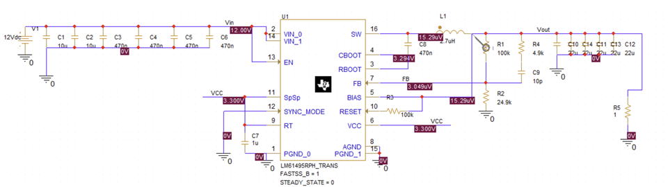
I am simulating the LM61495 in PSpice. My circuit (screenshot below) should be equivalent to the application example in the datasheet (fig 9-1 on page 32) with a 1 Ohm load resistor. However, I have an output of around 15mV.
I am new to PSpice for TI so there is a chance that I have a mistake in my simulation setup.

Does this circuit look ok? Why do I ovserve this (obviously wrong) output?

Thanks a lot for your help,

Michael

  • I think I figured it out. I underestimated the devices startup time and therefore my simulation was too short. Now the transient output graph looks good. I still don't understand what the bias point shown in the schematic is.

  • Hi,

    The original image may have been the voltage at the initial startup point which micro-volts which is basically 0V.

    If you reran the simulation again for longer period of time, the bias point should converge to the correct value.

    Regards,

    Jimmy