This thread has been locked.

If you have a related question, please click the "Ask a related question" button in the top right corner. The newly created question will be automatically linked to this question.

UCC3818: Maximum multiplier current

Part Number: UCC3818

Hi,

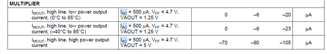
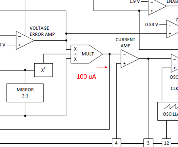
It is said in SLUS395K that maximum multiplier current is 315 uA for Figure. 9 but with RAC given as 750kOhm, IAC at Vmin of 85 V becomes 158 uA. If V_VFF is a 2:1 current mirror connected to the RC, then magnitude of VFF voltage becomes 2*IAC_min*(1/C/s) which is 0.38 V at low line.

Considering V_VAout of 5.5 V and K of 1, max current is 4.9 mA from equation (14) which is way higher that 315 u A. Which parameter am I entering wrong?

  • Hello Marzieh, 

    The V_VFF current mirror ratio of 2:1 is based on is IAC = 2*IVFF, in other words IVFF is half of IAC.  This is not very clear in the datasheet text. 
    But, see spec table: 

    Other things are also not clear in the text:
    Section 8.2.2.3 discusses solving for Riac as 750kR, but a few sentences later indicates that 2 x 383kR = 766kR is actually used.  That reduces Iac to 157uA.
    Section 7.3.5.14 indicates that Vff at Vin(min) should be set at 1.4V.  (Equation (11) uses that value to calculate Rvff.)

    So, equation (14) gives Imout(max) = 157uA x (5.5V-1V) / (1.4V)^2 = 360uA.  This is a lot closer to the 315uA obtained by eqn (14). 

    I'm not sure where the remaining discrepancy comes from.  If you use Vvaout(max) = 5V (instead of 5.5), you get 320uA. 
    Sometimes 5V is used for 100% load power and 10% extra is allowed for max power which drives Vvaout to its 5.5V limit. 

    I wish this datasheet was clearer in its design procedure, but it is an old one and I think the author at the time must have made some unstated assumptions (based on his prior experience) which are not explicitly discussed in the datasheet. 

    Regards,
    Ulrich

  • Thanks Ulrich. Your calculations matches section 6.5 of datasheet:

    However, I do not understand how Vff can be found from IVFF. I thought it is just VFF=(Rvff||Cvff)*IVFF but it does not look like that. I assumed IVFF is a sinusoidal with the amplitude of IAC/2.

  • Sorry. I did not pay attention that IAC is from the output of diode bridge. so the frequency is not 60 Hz on the voltage and it looks like frequency of ~2 Hz gives the right results. I do not know why this frequency should be used though.

  • Hello Marzieh, 

    IVFF is a current that is 1/2 the amplitude of the IAC current.  IAC is a rectified sine-wave, so its frequency is 120Hz.  IVFF is also a rectified sine wave. 
    A true sine wave has an average of zero, but a rectified sine does have an average value.   

    Because the PFC controller assumes that the input is a sine wave, it uses the average value of VFF to represent the RMS value of the input voltage.
    IVFF is filtered by Rvff || Cvff to obtain an average voltage that is proportional to Vin(rms).   

    The ideal average of a half-sine is 2/pi x the peak, and is a DC level.  However, the R-C filter cannot produce an ideal DC level, but produces the average level with a residual ripple voltage on it.  This ripple voltage affects the Imout current and adds distortion to the input.  In the datasheet page 19, the paragraph above equation (12) discusses how much ripple is allowed for a given THDi level.  The amount of ripple determines how low the filter pole must be which then  determines the size of the filter capacitance Cvff.  In the example case, the pole is around 2.6Hz to attenuate the ripple voltage sufficiently. 

    Choosing a lower pole would attenuate the ripple voltage even more, and have lower THDi, but would increase the size of Cvff, and worse, would slow down loop response to changes of input voltage.  So there is a trade-off to be made between loop-response to line transients and the amount of THDi that can be allowed.        

    Regards,

    Ulrich

  • Hopefully, last question:

    What is the direction of IMULT? Values are given as negative but I do not know for what direction.

  • Hello Marzieh, 

    It's interesting: someone else just asked this same question yesterday.
    See https://e2e.ti.com/support/power-management-group/power-management/f/power-management-forum/1312181/uc2854a-multiplier-output-current---direction 

    To answer directly: Imult current is OUT of the pin. 

    By convention, current is positive into a pin and negative out of a pin.  But sometimes, a positive number is listed for the maximum value (for example) even though the current that is being specified comes out of the pin.  In such cases, the direction should be noted in the test conditions. 
    If not, then the direction has to be inferred based on the circuit context (that is, which direction makes the most sense based on the circuit in which it is used).   
    But usually, the convention holds. 

    Regards,
    Ulrich