Other Parts Discussed in Thread: LM5176
Hi Team,
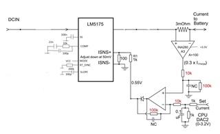
We have LM5175 which is used for charging a battery, 7 cells 25.9V 3.3A 86Wh.
In our design we want to control both output voltage and output current.
For voltage we are biasing feedback (FB) voltage with a voltage from a DAC.
This works fine. We can adjust voltage as we want.
We want to limit output current to a value we set by another DAC from 0.1A to 5A.
For current limit we use a 3mR shunt resistor and ISNS inputs.
The voltage over shunt resistor is amplified 100 times with INA280A3.
This voltage is compared to the desired voltage (desired current) from DAC with a differential amplifier.
We have PC software where we can set our desired values.
For electronic load this current limit works fine.
Example:
I set desired voltage to 27000mV. I set desired current to 500mA.
Electronic load is set to 200mA. Output is 26.9V. Converter is running.
Electronic load is set to 1A. Output is 6.42V. Converter has stopped.
Electronic load is set back to 200mA. Output is 26.9V. Converter is running again.
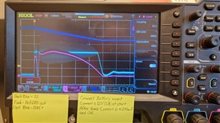
For battery load the converter does not start correctly if actual current is higher than desired current.
Example with a battery of about 25V. Current will be higher than 500mA if 27V is applied.
I set desired voltage to 27000mV. I set desired current to 500mA.
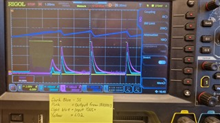
This picture is after about 16ms and SS has raised above 0.8V.
Current goes up and above 50mV on ISNS+ very fast and SS is pulled down. PWM stops. Current decreases.
SS starts to increase and the procedure continues.
Converter will never start properly.
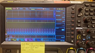
If the converter is started and actual current is lower than desired current, then it works/starts.
If the converter is working and I thereafter set to 27V and current limit to 500mA then it works.
Here I can hear audible noise of about 3kHz, regulation frequency.
I know it don't make sense with my settings like "desired current" instead of actual volt but I hope you get the feeling of how it behaves.
Best Regards
Terho