This thread has been locked.

If you have a related question, please click the "Ask a related question" button in the top right corner. The newly created question will be automatically linked to this question.

LMZ13610: LMZ13610 schematic diagram

Part Number: LMZ13610

Hi,

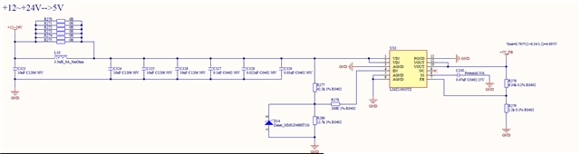
The design schematic diagram of LMZ13610 is shown below. Could you please help check if there are any issues? Or good advice?

  • Hi Jeno,

    1. Output capacitors are missing. One recommended output capacitor combination is two 330-μF, 15-mΩ ESR tantalum polymer capacitors connected in parallel with a 47-uF 6.3-V X7R ceramic. This combination provides excellent performance that may exceed the requirements of your applications and you can decide based on your actual test results. Additionally some small 47-nF ceramic capacitors can be used for high-frequency EMI suppression. 

    2. Leave the place for a 50ohm resistor between VO and the upper feedback resistor R276 in case the loop test is needed.

    3. Leave the place for a feedforward capacitor across the upper feedback resistor R276 to help tune the loop.

    You can also take a look at the EVM user's guide for the reference. 

    https://www.ti.com/lit/ug/snva478c/snva478c.pdf?ts=1705311393539&ref_url=https%253A%252F%252Fwww.ti.com%252Fproduct%252FLMZ13610 

    - Hongjia