


Hi,
I tested TPS56C215 static load ripple and efficiency under Vin=5V and 12V / Vout=0.75V with TPS56C215 EVkit
Vin=5V is more efficient than Vin=12V as datasheet mentioned.
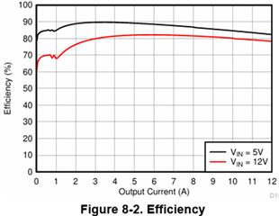
1) Is there any reason why Vin=5V is more efficient?
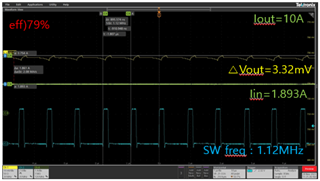
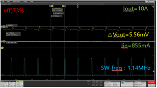
2) And please let me know why Vout ripple is larger (about 2mV) when Vin=12V than Vin=5V? (Iout=10A)
Vin=5V -> △Vout=3.32mV
Vin=12V -> △Vout=5.56mV
3) Is it stable response with this ringing? Could you let me know how much phase margin is with this ringing?
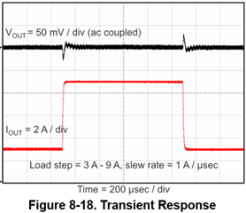
4) Which equipment did you use for test transient response?
I don't have the stability analyzer equipment so I want to test transient response with load step.
But with my equipment, it's slew rate is not set fast enough to see the difference according to the Cff.

