This thread has been locked.

If you have a related question, please click the "Ask a related question" button in the top right corner. The newly created question will be automatically linked to this question.

LP8555: 8 serial RGB LED => driver search

Part Number: LP8555
Other Parts Discussed in Thread: LP5520, LM3697, LM3532

Dear TI technical support,

I contact you because I'm looking for a specific LED driver. 

And after several hours of research, It seems that it is not so easy to find what I'm looking for.

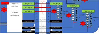
I'm looking for a driver which could be like the one just below (to manage 8 deported RGB LEDs).

The goal is to manage the LED in serial in order to limit the number of contacts between the main board where is located the Driver and the LED board where are located the 8 RGB LEDs.

The technical inputs and requirements are the following :

Supplier into the panel

Number of
Current source Channel

Current source level per channel
[mA]

Vin
[V]

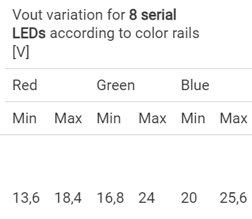
Vout variation for 8 serial LEDs according to color rails
[V]

Topology

Number of integrated boost

Interface

Package

Global
efficiency
[%]

MOQ

Lead Time
[Weeks]

Perennity
[Years]

Price
[€]

Red

Green

Blue

Min

Max

Min

Max

Min

Max

Requirements

Yes

3

20

5,25V
+/- 5%

13,6

18,4

16,8

24

20

25,6

Boost

between 1 to 3 if possible to limit power dissipation

I2C for 3 channel PWM configuration

Shall match with our dissipation constraints

> 80%

< 1000

< 10

> 5

< 1€

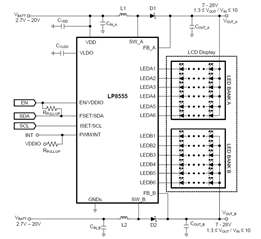
The LP8555 is nearly in line with me need but I 'm a little bored to use only 3 currents sources in on 12.

It is not optimized

I have seen an other chip (LP5520) which is more closed to my need in terms of current sources but not in line with :

 - the output voltage that is requested in my case (Max 25,6V).

- the power optimisation with different boost output values (nevertheless, I think one common Boost for all RGB colors could be acceptable because I have only 20mA per string).

Could you provide me the most appropriated reference regarding my need?

Thank you for your feedback.

Best regards.

Anthony 

  • Hi Anthony,

    At the first glance at your requirements, I think you could consider LM3697 which is a 3 channel LED driver with up to 30mA per channel and up to 40V Vout.

    LM3697

    BR

    Patrick

  • Thank you very much for your advice Patrick.

    This component is closed to what I'm looking for, except that I would like to have a dedicated PWM on each LED channel.

    I forgot to insist about this in my initial request.

    Do you have a component in your mind to match with this additionnal requirement?

    Thank you for your support.

    Anthony.

  • Hi Anthony,

    May I know if I2C is also acceptable for you?

    BR

    Patrick

  • Hi Patrick,

    Having a I2C configuration would be the best solution for me as my processor plateform is limited in terms of PWM. 

    I'm not sure to be able to have 3 PWM free for this.

    I2C configuration to manage 3 different PWM on the chip driver would be the best configuration for me.

    Best regards.

    Anthony.

  • Hi Anthony,

    LM3697 can only have two control bank to control the current separately so that 3 channels will be divided into 2 groups. If you really need the 3 channels to be independent, then LM3532 might be a better choice for you.

    LM3532 data sheet, product information and support | TI.com

    BR

    Patrick

  • Thank you Patrick,

    LM3532 seems to be clearly the best solution for me.

    I have 2 questions for you for my perfect understanding:

    - Could you confirm that LM3532 can offer  an Independent Current String Brightness Control even if I don't use external PWM pins?

    - Could you give me your feeling regarding the power dissipation in my RGB application? In fact I have a voltage variation from one string to another one.

    Worst case is around 12V between  Red Rail voltage min and Blue Rail voltage max.

    => It means that the Headroom voltage will be completly respected but very high and it could lead to have a power dissipation of 12V*20mA = 240mW additional power dissipation in the current source for Red rail, and a little less for Green LED rail.

    It seems that the component should accept this voltage and this power dissipation (even if we work @ 65°C worst case) .

    Thank you in advance for your advice on this point according to your experience.

  • Hi Anthony,

    1. Yes, you can control the 3 channels current separately without PWM, only need I2C.

    2. Consider the worst case (Blue 25.6V, Green 16.8V, Red 13.6V), the total power loss on current sink will be ~420mW, and the Boost converter power loss is ~270mW (85% efficiency). So the junction temperature will increase ~43°C higher than ambient. It seems okay that it is still in the 125°C recommended operation range.

    BR

    Patrick

  • Thanks a lot for all these confirmation Patrick. That is very clear.

    A last question before closing definitely this item.

    I don't find the same power loss ~270mW (85% efficiency).

    1/ Page 40, I can find an efficiency curve for Vin = 5V (my case), an number of LED = 9 with Vf= 3.2V (my case) for Triple String.

    => It gives a 90% efficiency in my case. Could you confirm you are in line?

    2/ However, even if I consider 85% instead of 90% in don't find power loss in the boost = 270mW.

    => On my side, I have considered power to provide = (VLED BLUE MAX + VLED GREEN MIN + VLED RED MIN) * I LED 

    With VLED BLUE MAX   = 25.6V

            VLED GREEN MIN = 16.8V

            VLED RED MIN      = 13.6V

    AND I LED = 20 mA

    Could you provide me the detail of your calculation for the global power which is considered on the Boost?

    If I consider 270mW for the boost loss, then I'm in line with the temperature increasing calculation and the conclusion in front of the Max Thermal junction temperature...

    Thank you for your last confirmation.

    Best regards.

    Anthony 

  • Hi Anthony,

    1.  I chose 85% just to make the case much worse so that we can have more margin for the real board. 

    2. For the boost power loss, the max Vout is 25.6V, and each string has 20mA, so the total power of boost output side will be 25.6*20*3=~1.5W, consider 85% efficiency, the power loss of boost is 1.5/0.85*0.15=~270mW.

    In fact, the 270mW will not only dissipate on IC, the inductor and diode will also share the power loss. So consider the 270mW all on IC is just to make the case much worse for more margin.

    BR

    Patrick

  • Thank you Patrick.

    I'm 100% in line with you.

    Thank you for this technical sharing.

    It was a pleasure to discuss with you and to have your support.

    Best regards.

    Anthony.