


Hello everyone,
We are currently developing an accumulator management system based on the BQ79612-Q1. Our first approach is to build a master module consisting of our microcontroller (STM32G474) and one BQ79612 as a base device. This base device will later form the interface between our controller and the other BQ79612s, which are located on slave boards, each attached to a battery cell stack.
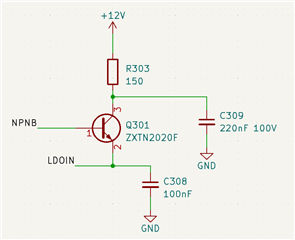
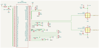
We are currently facing a lot of problems in establishing a connection between your chip and our microcontroller. Let me explain our current status: We have developed a small pcb as a prototype for our master module mentioned above. It includes a power supply, our microcontroller and your chip. The circuit, that is connected to the BQ79612, is shown in the picture below. Note that we use level shifters to match the 5V logic level to our microcontroller.
We are able to wake up the BQ79612 by sending the wake ping as described in the datasheet. When we try to read any register, for example using the command to read out the part id (hex: 80 00 05 00 00 35 DF -> created with your online tool), we do not get any response. We have double checked that the bits sent are received by the BQ using an oscilloscope at the RX pin.
I would highly appreciate if you could give us tips and hints on how to proceed. Are there any hardware errors in our schematic, are we missing something?
Thanks in advance, best regards
Nick
