This thread has been locked.

If you have a related question, please click the "Ask a related question" button in the top right corner. The newly created question will be automatically linked to this question.

TPSM8D6C24: How to determine I/V loop gain value

Part Number: TPSM8D6C24

Hello,

My customer is using TPSM8D6C24MOWR in the two cases below.

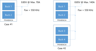
Q1. Please tell us the appropriate V-Loop Gain and I-Loop Gain setting values for 2 and 4 Bucks in Case #1 and Case #2, respectively.

Q2. Please tell us how to determine the I/V loop gain value if the voltage or usage structure changes.

Thank you.

JH

  • Hi JH

    Looking at your topologies, these topologies are already explained in Application section of the datasheet

    https://www.ti.com/lit/ds/symlink/tpsm8d6c24.pdf?ts=1706025055080&ref_url=https%253A%252F%252Fwww.ti.com%252Fproduct%252FTPSM8D6C24

    For V loop gain and I loop gain refer to the sections  6.3.1.2 and 6.3.1.3 of the TPSM8D6C24 data sheet and the module uses TPS548D24A IC and is s better to use the excel calculator for TPS548D24A with 220uH integrated inductor

    excel calculator:

    https://www.ti.com/product/TPS546D24A?utm_source=google&utm_medium=cpc&utm_campaign=app-bsr-null-44700045336317446_prodfolderdynamic-cpc-pf-google-wwe_int&utm_content=prodfolddynamic&ds_k=DYNAMIC+SEARCH+ADS&DCM=yes&gad_source=1&gclid=EAIaIQobChMIxaS_xf_zgwMV1zbUAR0cJA3YEAAYASAAEgJSvfD_BwE&gclsrc=aw.ds#design-tools-simulation

    Thank you

    Savith

  • Hi Savith,

    Thanks for your reply.

    The customer checked the datasheet and excel file provided, but they did not think it was clear how much the V/I Loop Gain value should be entered.

    Below are the customer's answers and additional inquiries.

    In the datasheet, there is an ILOOP value recommended by TI for each Fsw. (Table 7.2, Eq.5)

    And VLOOP can be obtained through several functions. (Eq. 10)

    Additionally, a low ILoop gain is recommended through Note.

    If they enter the Target value of the V/I LOOP in the provided Excel sheet as shown below, they will be informed of the appropriate setting method (a constant must be entered).

    Q1. Please briefly explain the meaning of ΔVout, ΔIout, and CSA in Eq.10.

    Q2. When designing Fsw = 550KHz 2-Phase, Imax 70A, please check whether the Loop Gain below is appropriate.

    • BUCK 1 : ILOOP GAIN = 4, VLOOP GAIN = 2 (MSEL1, Config 13)
    • BUCK 2 : ILOOP GAIN = 2, VLOOP GAIN = 2 (MSEL1, Config 3)

    Q3. When designing Fsw = 550KHz 4-Phase, Imax 140A, please check whether the Loop Gain below is appropriate.

    • BUCK 1 : ILOOP GAIN = 2, VLOOP GAIN = 2 (MSEL1, Config 3)
    • BUCK 2 : ILOOP GAIN = 2, VLOOP GAIN = 2 (MSEL1, Config 3)
    • BUCK 3 : ILOOP GAIN = 2, VLOOP GAIN = 2 (MSEL1, Config 3)
    • BUCK 4 : ILOOP GAIN = 2, VLOOP GAIN = 2 (MSEL1, Config 3)

    Q4. Please let us know what symptoms may occur if the V/I Loop Gain setting is inappropriate.

    Thanks,

    JH

  • Hi JH
    I am looking into the above question and will get back to you tomorrow

    Thank you

    Savith

  • Hi JH,

    Q1. Please briefly explain the meaning of ΔVout, ΔIout, and CSA in Eq.10.

    They are the load transient requirements. ΔVout represents the drop in Vout, while ΔIout represents the increase in load current. CSA is the gain of the current sense amplifier, and it has a gain of 1/CSA or 1/162.5 A/V, and CSA is equal to 6.155mV/A.

    Q2. When designing Fsw = 550KHz 2-Phase, Imax 70A, please check whether the Loop Gain below is appropriate.

    • BUCK 1 : ILOOP GAIN = 4, VLOOP GAIN = 2 (MSEL1, Config 13)
    • BUCK 2 : ILOOP GAIN = 2, VLOOP GAIN = 2 (MSEL1, Config 3)

    When stacking converters that share the same output, it is not possible to have different ILOOP values. The follower converter will receive it's compensation configuration through BCX pins. The recommended ILOOP gain for TPSM8D6C24 switching at 550kHz is 6 (as shown in the Table 7-2). Setting ILOOP to 2 (instead of 6) will limit the voltage loop bandwidth to 87kHz/3 = 29kHz. The minimum VLOOP gain will depend on the required VLOOP gain from Equation 10 based on the load transient requirement. The maximum VLOOP gain will depend on the output capacitor impedance at the maximum voltage loop bandwidth frequency, adjusted for the lower ILOOP gain selected.

    ZCOUT @ max voltage loop bandwidth < CSA x 1/(VOUT_SCALE_LOOP x VLOOP x # of phases) 

    Q3. When designing Fsw = 550KHz 4-Phase, Imax 140A, please check whether the Loop Gain below is appropriate.

    • BUCK 1 : ILOOP GAIN = 2, VLOOP GAIN = 2 (MSEL1, Config 3)
    • BUCK 2 : ILOOP GAIN = 2, VLOOP GAIN = 2 (MSEL1, Config 3)
    • BUCK 3 : ILOOP GAIN = 2, VLOOP GAIN = 2 (MSEL1, Config 3)
    • BUCK 4 : ILOOP GAIN = 2, VLOOP GAIN = 2 (MSEL1, Config 3)

    See explanation above. Only thing that changes is the # of Phases.

    Q4. Please let us know what symptoms may occur if the V/I Loop Gain setting is inappropriate.

    If ILOOP gain is set too high, the switching ON time may alternate between long and short pulses, leading to subharmonic instability. If the VLOOP / ILOOP gain is set too high, the output may have low phase margin or oscillate in instability. If VLOOP is set too low, transient response may not meet the requirement. 

    Thank you,
    Tomoya