Hi, TI experts
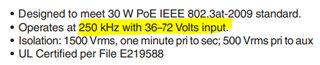
There is a request for technical inquiry from a customer regarding the use of TPS23754PWP in an RFID model.
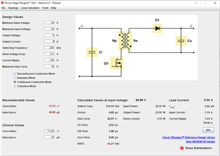
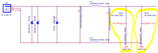
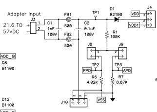
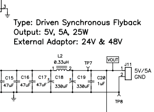
The customer's RFID model operates by ORing the POE power and DC power to the TPS23754 to produce 5V output.
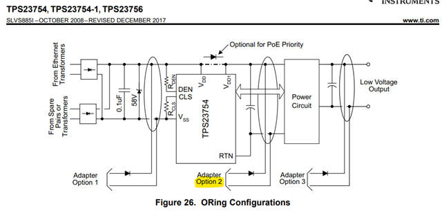
DC power is located in Option 2 of Datasheet_Figure 26 of TPS23754, and POE is designed to operate even when DC power is applied.
CE certification of the RFID model is currently in progress, but it is failing when DC power is applied.
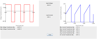
The problem is that noise at a frequency that is a multiple of 240KHz bounces around.
It has been confirmed that disconnecting the connection between TPS23754 and the DC line, and instead connecting an external DC-DC converter, eliminates the problematic noise when the 5V output is operational.
The conclusion is that the issue is attributed to the switching frequency (240kHz) generated during the operation of TPS23754PWP.
Below is the debugging content tested to solve the problem. (There was no effect at all)
1. Remove noise by connecting a common mode inductor (240KHz / 6K Ω) to the DC power line → No effect.
2. Remove noise by connecting a 22uF decoupling capacitor to the DC power line → No effect.
3. Connect Bead to DC power line (240KHz / 1K Ω) → No effect.
4. Wrap Ferrite Core around Adapter Power Cable and Test → No effect.
Q1) Could you please confirm if there are any additional debugging considerations other than the test contents above?
Q2) Is there a guide to reduce noise?
Please check how to improve or what needs to be reviewed.
Thank you.