This thread has been locked.

If you have a related question, please click the "Ask a related question" button in the top right corner. The newly created question will be automatically linked to this question.

UCC28911: efficiency and maximize output power

Part Number: UCC28911
Other Parts Discussed in Thread: UCC28750, UCC28700, UCC28710, PMP30026

hello actually we use a secondary isolated flyback solution and we are looking renew our old design : 

target : 10 to 12W output power, 230VAC 50Hz , 12 years production starting from 2025, good efficiency, isolated output power, low cost, compact form factor 

our first selection went to UCC28911

questions :

1 - is the production is guaranteed for the next 12 years for the UCC28911? 

2 - can we boost it's actual 8W output capabilities to 10 or 12W by raising the output voltage to 10 or 12VDC 1,5A???( the output voltage of the PSU go to power 2 DC/DC with 12V input capabilities) ?

3 - Is that the perfect match ?

4 - compared to other solutions (secondary side) the efficiency is higher (>80% )compared to the UCC28911 (78%) is there a reason for that ?

looking forward for your feedback 

Best regards

  • Hi Ziad,

    Thank you for the querry on UCC28911.

    1. That's difficult to answer. But definitely it is a part which is popular and it is usd by a number of customers. Definitely, there will be upgrades to this IC with more compact packages and better FETs integration.

    2. We have a reference design which is 12V/1A (12W), but 12V at 1.5A is going to be very difficult. Ultimately it is going to depend on the thermals and ambient temperature and definitely there should not be any casing. According to the datasheet, maximum continuous power with open frame design at 50°C ambient, with adequate copper area (probably > 500mm^2) connected on GND pin and /or adequate air flow to have 50°C/W as junction to ambient thermal resistance. So it will be difficult to increase output power.

    3. It might not be a perfect match if you are considering to renew your old solution.

    4. The other solutions might use discrete external FET which might have better figure of merit than the internal FET of UCC28911 and hence may be slight difference in efficiency.

    Please let us know  if you have questions.

    Regards,

    Harish

  • Hello Harish and thanks for your detailed answer,

    1- Our design is targeting 2025 market, do you have a road map to share about the new products to be released?

    2 - a 12 or 14W solution are our target. in all cases we will have peak power consumption at 12 or 14W during the gsm broadcast but it will not be permanent...  and our product is for consumer, 50°C ambient is acceptable. to be added we have actually 600mm2 on the HVGND as recommended in the design ... i did not found the reference design for the 14W / 12V output ... can you share it please .?

    3 -  based on your website component selector, it is the single option in primary side regulation ... can you recommend another reference to evaluate ? we are open to evaluate new releases in the coming month ... 

    4 - good to know

    Looking forward for your feedback and thanks for your support

    Thanks

  • Hi Ziad,

    Thank you for the reply.

    1.  We have a roadmap for AC-DC products, but unfortunately I will not be able to share it here due to NDA restrictions. But one product which recently released is UCC28750 which is extremely low cost flyback controller IC. But this will need external FET and can easily support the required voltage and power levels. Another downside is this one is secondary side regulated. Have reached to our field team, they can probably help with the roadmap?

    2.  The following is the reference design which I mentioned.

    UCC28911

    https://www.ti.com/lit/df/tidrln6/tidrln6.pdf?ts=1706180425974&ref_url=https%253A%252F%252Fwww.ti.com%252Freference-designs%252Findex.html

    UCC28700

    https://www.ti.com/lit/df/tidrry5/tidrry5.pdf?ts=1706181900968&ref_url=https%253A%252F%252Fwww.ti.com%252Freference-designs%252Findex.html

    https://www.ti.com/lit/df/sluraf5/sluraf5.pdf?ts=1706181985827&ref_url=https%253A%252F%252Fwww.ti.com%252Freference-designs%252Findex.html

    https://www.ti.com/lit/df/tidry22/tidry22.pdf?ts=1706182096835&ref_url=https%253A%252F%252Fwww.ti.com%252Freference-designs%252Findex.html

    UCC28911 needs to be evaluated throughly through qualification process as this will be going into the product rather than a proof of concept reference design like what we demonstrate for this power level. Yes, 600mm^2 should be ok.

    3. One thing I can say is we definitely have some intersting switcher options in concept/ definition which are primary side regulation but none of them are going to be available anytime this year. So the best PSR options with switch are UCC28911 as you have already selected or UCC28700/UCC28710 controllers with external switch is the other option.

    Please let us know if you have questions.

    Regards,

    Harish

  • Thanks Harish for your detailed feedback 

    I will be willing to evaluate the PMP30026

    i have two questions :

    1 - D100 (SMAJ58A) & D101SMAJ75A) : by a single SMAJ130A ?? or there is other considerations that i missed ? 

    2 - the PMP30026 integrates an isolated voltage measurement block given for 5%, if we calibrate it during production, can we achieve 0,1% between 170 and 250VAC?

    once again thanks for your support 

    Ziad


  • to be more precise i am willing to use from ST : SMBJ130A-TR or 140 if you are aligned with my proposal,
    to be precised, the efficency is a key element, 

  • Hi Ziad,

    Yes, you can use a single TVS clamp suggested above instead of two nos. and there should not be any issue. Depending on Vds spike if the clamp is oo aggressive, maybe the during the leakage reset time this clamp diode might get hot (so need to check from a thermal point of view).

    On the voltage sensing part, I am not sure on the accuracy, although I feel with calibration <0.5% should be possible. Maybe an opamp/ sensing group might give better explanation.

    Please let us know if you have further questions.

    Thank you

    Regards,

    Harish

  • Hello HArish 

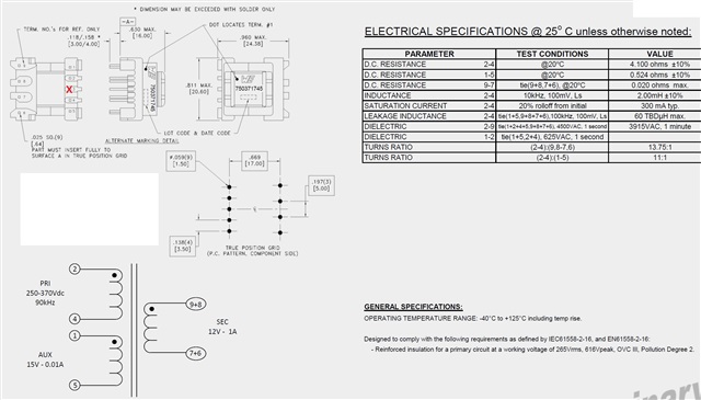
    working with our transformer supplier we got the following proposal for our 12V/1A design ? 

    do you have any comments before proceeding for sampling please ? 

    best regards

  • Hi Ziad,

    Thank you for reaching out. 

    The turns ratio calculates to 13.75 for a minimum input bulk voltage close to 135V. I am not sure on the Ripk and peakcurrent allowed, but 2mH looks high as this might push Fsw down to lower FM region (unless you prefer to operate at lower frequencies intentionally) according to P = 0.5Li^2Fsw. You might want to check this. The reference designs which I pointed out earlier also seem to use a lower value of 800uH to 1mH.

    Regards,

    Harish

  • Helo Harish 

    we are tageting only EU market with 240VAC ( 250 to 360VDC) is that has an impact on your feedback 

    still transformer need to be updated ? 

    we take a particular attention to the efficency, so please advise to optimise our use case

    best regards

  • Hi Ziad,

    The minimum input voltage is 250Vdc, so Nps = (Dmax x Vbul_min)/(Dmagcc x (Vout+Vf)) = 0.48 x 250/(0.413 x 12.5) = 23.

    So reducing the turns ratio might cause allowable Dmax to reduce, which can increase RMS currents which can affect efficency. But practically designing for Nps =23 might make Ripk large and limit the peak current.

    So considering these tradeoffs, I think Nps of 13.75 is ok. Just make sure Ripk is chosen so that Ipk is sufficient to operate in the upper FM region for the best performance. What was the switching frequency the prototype you had designed to operate?

    Thank you

    Regards,

    Harish

  • Thanks Harish

    in fact i just copied the ref design of the PMP30026, so i will be using the same configuration with only 240VAC

    in this case you advise me to go with the proposed transformer from my supplyer as it is ? 

    best regards

  • Hi Ziad,

    PMP30026 follows the following analogy:

    Nps = 0.482*100/(0.413*12.5) = 9

    Ripk = 9 x 0.5 x(260/1) = 1170 ohms

    Lm= 2 x 12/ (0.9 x 105000 x (640/1170)^2) = 850uH

    Ipk = 550mA

    Using a similar analogy for your case of 240Vac, Nps =22 (Lm might be higher for this case, around 5mH with reduced peak current for Ripk)

    Ripk = 1.78kohms (for Nps =13.75) gives Lm = 1.9mH, Ipk =360mA

    I think your calculations hold good and transformer looks fine and it will work without any issues as you have in your proto unit, but Dmax will be limited with slightly more RMS currents.

    Thank you

    Regards,

    harish

  • Thanks Harish for your support, I will update the RIPK to 1,78K and test with the proposed transformer, i will keep you posted with the result

    Ziad

  • Thank you Ziad, Please feel free to ping when you have any questions. I will close this thread for now.