This thread has been locked.

If you have a related question, please click the "Ask a related question" button in the top right corner. The newly created question will be automatically linked to this question.

BQ27426: FuelgaugeIC can correctly match the true SOH range of the battery

Part Number: BQ27426

Hello,

We have communicated with TI Shanghai FAE regarding the results:

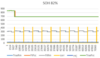
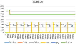
The actual SOH value of the battery is greater than 80%, and after insertion into the device, there is no need for complete charging and discharging. There is charging and discharging process, and the Fuelgauge IC can match the FCC of the battery.

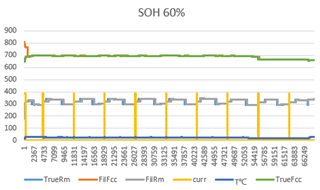
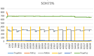
The actual SOH of the battery is less than 80%. After inserting the device, it is necessary to fully charge and discharge the battery to match the fuel gauge IC with the battery's FCC.

1, Is the above statement correct?

2. if it is incorrect, 80% should be changed to what %?

  • #1: It's an incomplete statement. The gauge will have to learn Qmax and Ra and this requires N number of full charge/discharge cycles. N is a function of age (SOH). So this can be accurate after 1 cycle or it can take 2 or ... N cycles. If SOH is high (>80%) then the initial error may be trivial, hence I assume the Shanghai FAE answered as such.

    #2: The gauge will only be accurate without cycles if the cell is as new as the one that was used to generate the Golden Image. So that's the % that you need to use, if you want best accuracy. If SOH for the cell for the Golden Image was 98%, then that's the threshold for cells that won't need a cycle for the gauge to be accurate.

  • hello,

    We tested with a battery whose SOH is high (>80%)和SOH is low(<80%), presenting the following phenomenon.

    After loading the Fs file (reserve capacity 350mAh, design capacity 1230mAh), the TRUE Fcc obtained is 851mAh, and when we start charging, the TRUE Fcc changes to 695mAh.

    May I ask, which parameter changes caused the TRUE Fcc change?

    FCC_Test_log_2.zip

  • Please make sure that V at Chg Term is set correctly. Charge Termination will affect FCC.

  • hello,

    Thanks for the support.

    We have verified that modifying V at Chg Term to 4400mV reduces the reduction of TRUE FCC at the start of charging.

    1, Is V at Chg Term a factor that causes the FCC to not match the true capacity of the battery during charging and discharging?

    2、According to the provided logs, what other register parameters can be identified as factors that affect the FCC not matching the true capacity of the battery?

  • #1: V at Chg Term determines the depth of discharge of the cell that the gauge considers a full charge. Hence it is critical to correct FCC.

    #2: If the gauge is configured correctly, estimated FCC will match the total passed charge from a full charge (which is determined by the voltage at charge termination and the taper rate) to cell voltage dropping below Terminate Voltage. This is how FCC is defined. I'm not sure what you mean with "true capacity of the battery". There's Design Capacity, a nominal value from the cell manufacturer, which gives you an idea of total charge that you can get out of the battery under nominal conditions. And there's Chemical Capacity, which is the no-load theoretical charge between DOD of 0 and 1. What do you mean with "true capacity of the battery"?

  • Hello,

    The true capacity of the battery is:
    The discharged capacity of the battery recorded by using a charge/discharge meter, charging and discharging at 0.2C current, and the battery voltage discharged from 4.4V to 3.3V.

    The question I would like to ask is: after inserting a new battery (TRUE FCC should be 1230-350) and TRUE FCC drops to 695mAH, I continue to perform multiple charge/discharge cycles, but the value of TRUE FCC does not change and does not match the true capacity of the battery.
    What other factors besides V at Chg Term can affect TRUE FCC to follow the true capacity of the battery? Please help with a detailed list.

    #2: If the gauge is configured correctly, estimated FCC will match the total passed charge from a full charge (which is determined by the voltage at charge termination and the taper rate) to cell voltage dropping below Terminate Voltage. This is how FCC is defined. I'm not sure what you mean with "true capacity of the battery". There's Design Capacity, a nominal value from the cell manufacturer, which gives you an idea of total charge that you can get out of the battery under nominal conditions. And there's Chemical Capacity, which is the no-load theoretical charge between DOD of 0 and 1. What do you mean with "true capacity of the battery"?
  • for the gauge to be accurate, you'll have to make sure that the load prediction is set to predict a 0.2C current, the V at Chg Term matches the charging voltage that you used, the Taper Rate setting matches the taper current that you used to charge the cell to full and that Terminate Voltage is set to 3300mV and Delta Voltage is set to 0mV

    Here is the detailed list:

    * V at Chg Term

    * Taper Rate

    * Load Select

    * Terminate Voltage

    * Design Capacity

    * Qmax

    * Ra

    Note that V at Chg Term, Qmax and Ra are learned. They must be correct for a specific cell. If you use an aged cell, Qmax and Ra will have to be learned through N cycles. V at Chg Term must match your charger settings.

  • Hello,

    You replied earlier about the main rules for Qmax and Ra updates.

    Qmax:

    1. Relax until voltage is stable at a high or low DOD (>0.9 or <0.1)

    2. Pass enough charge between relaxations (at least 37% of Qmax)

    3. Make sure that temperature is between 10deg.C and 40deg.C

    4. This has to be within a reasonable time (e.g. not a whole day of a single discharge with a C/24 current).

    Once the gauge updates Qmax, then you have to make sure that Ra updates. The main rules are:

    1. Qmax is correct (the gauge will disable resistance updates if Qmax is grossly incorrect)

    2. Current is >C/10

    3. Discharge is long enough for DOD to change by approx. 0.1

    After loading the FS file, I have a few questions about the Qmax and Ra update conditions:

    1, The main rules of Qmax, do they all have to be satisfied or is it sufficient to satisfy one of them?

    2.Qmax In addition to the above rules, what other rules need to be met? Please help to list them in detail and tell how to confirm that the rules have been met?

    3, The main rules of Ra, do they all have to be satisfied or is it sufficient to satisfy one of them?

    4.Ra In addition to the above rules, what other rules need to be met? Please help to list them in detail and tell how to confirm that the rules have been met?

    5, Will RA be updated only after Qmax is updated?

    6. Do VOK and RUP_DIS have to be equal to 0 for RA to be updated?

    7, What are the conditions for VOK = 0? How many v of voltage, how many seconds of maintenance time, other details of the conditions, etc.

    8, What are the conditions for RUP_DIS = 0? How many v of voltage, how many seconds of maintenance time, other details of the conditions, etc.

  • #1, #3: They all have to be satisfied.

    #2, 4: Those are the rules.

    #5: Ra will only update if Qmax updated at least once. UpdateStatus = 0x00 will configure the gauge to consider Qmax having been updated at least once in a learning cycle so a GoldenImage usually, by definition, doesn't require another Qmax update before Ra updates.

    #6: The gauge will not update Ra if RUP_DIS = 1. This bit will be zero at the start of discharge but if it turns 1 during a discharge, the gauge will disable Ra updates.

    #7: This is proprietary information. The gauge will set this bit if conditions are right. From a customer's point of view, what this means is that cell voltage must be stable in relax (not change by more than 1uV/s) and that the voltage is not in a flat zone (ChemID dependent, this is hidden by design) and that temperature must not be too hot or cold.

    #8: If Qmax is valid, RUP_DIS will be 0 at start of discharge.  RUP_DIS will be 1 during discharge if the gauge calculates negative resistance (e.g. the measured voltage under load is higher than the OCV for a grid point DOD). This can be due to incorrect DOD (e.g. incorrect OCV reading or incorrect Qmax or incorrect coulomb count calibration) or incompatible ChemID or insufficient load current.

  • Hello Dominik,

    Prerequisite: Qmax update requires charging\discharging more than Design Capacity*37%

    Q1:Is the charge\discharge cumulative?

    Q2:If it is cumulative, what is the maximum amount of time that can elapse between two accumulations?

    Q3:If it is cumulative, what is the minimum amount of mAh that can be charged\discharged between two accumulations?

    Q4:If it is cumulative, what is the maximum number of times it can be cumulative?

    Q5:The charging\discharging capacity does not exceed 37% of the Design Capacity*, but the SOC reaches 99%, will Qmax re-simulate?

    Q6:Is there any requirement on the charging/discharging current if the charging/discharging capacity exceeds 37% of the Design Capacity*?

    Q7:How many rounds of charging\discharging over Design Capacity*37 can be performed to make Fcc correctly match the true capacity of the battery for a battery with SOH=80% (more than 80% of a new battery)? What is the basis?

    Q8:If there is a reserve capacity, is the charging and discharge the design capacity * 37% or (design capacity - reserve capacity) * 37%?

    Q9:As the battery ages and the true capacity of the battery is less than Design Capacity*37%, does it still need to meet Design Capacity*37% for Qmax to be updated?

    Q10:As the battery ages, do the conditions for updating Qmax (design capacity * 37% charge throughput) change in equal proportion?

    Prerequisites: Ra table update requires Qmax to have been updated

    Q11:When using FuelGauge it will load the Fs file, the FS file has already learned the Qmax, is it considered that the Qmax has been updated and the Ra table can be updated directly when discharging?

    Q12:With FuelGaugeIC, after the entire Ra Table is updated, when updating the RA table again, is it still necessary to update Qamx first?

  • A1: It is between two OCV measurements. Note that if you charge and discharge, the total charge is the signed sum (so this would be zero, if you charge exactly the same amount as you discharge).

    A2/3/4: I'm not sure what you mean with accumulations in this context. The gauge calculates an error which depends on the coulomb counter deadband, the sense resistor and the capacity of the cell. This error will grow over time and it must not exceed a threshold (0.1% of Design Capacity by default). This time is usually >24 hours.

    A5: Qmax is measured, not simulated. It will not update if the passed charge between OCV measurements is < 0.37% of existing Qmax. It does not depend on SOC.

    A7: This depends on how different the cell's Qmax is from the configuration. The gauge applies both a maximum limit and a filter to Qmax. It limits changes to 20% of Qmax. And it filters Qmax with a dynamic filter coefficient for a 1st order IIR filter. The dynamic filter coefficient depends on the ratio of Design Capacity and passed charge. How this works in detail is proprietary information and can't be shared on E2E.

    A8: Reserve capacity is irrelevant to Qmax updates. The 37% threshold is relative to Qmax (it is actually a change in DOD (0.37 change) with change in DOD = passed charge / Qmax).

    A9/10: The required passed charge will diminish with measured Qmax.

    A11: Yes. This is indicated with UpdateStatus = 0x00

    A12: No.

  • Hello Dominik,

    Thank you for your support.

    1, Is it possible to understand that Design Capacity*37% of the pass-through charge requires continuous charging or discharging?

    2、Design capacity*37%的通过电荷,对充电电流或放电电流有限制吗?

    2、Is there a limit on charging or discharging current for Design capacity* 37% of the pass through charge?

    3、We actually verified that the charge current or discharge current is set to 1.2A and the passedcharge exceeds the Design capacity*37%, but the Qmax is not updated. Please help to confirm what is the reason?

    For logs, please check the attachment.

    4、We actually verified that after loading the Fs file,UpdateStatus=0x00, first Relax for more than 5 hour, then perform discharge, the discharge is greater than DOD 0.2, but Ra is not updated. After charging again to bring Qmax up to date, Ra changed during discharge. Doesn't quite match your reply, why?

    A11: Yes. This is indicated with UpdateStatus = 0x00

    5、How to confirm the correspondence table of OCV and DOD is correct? Is the correspondence table between OCV and DOD correct in our Fs file?

    37%_Qmax_0213_1-2A.zip

  • #1: It's not Design Capacity. It's 0.37 change in DOD and DOD is a function of Qmax.

    #2: The current has to be above the charge or discharge current threshold.

    #3: Your ChemID (2389) has an OCV flat zone between 3679mV and 3803mV. Your log file shows that the initial OCV measurement was done at 3759mV, which is inside this flat zone and therefore disqualified for Qmax updates.

    #4: The grid point crossing (DOD change) is only one requirement. Another one is that RUP_DIS isn't set by the gauge. If Qmax is inaccurate, the gauge will not have correct DOD and OCV(DOD) can be incorrect. If OCV(DOD) is lower than measured voltage, the gauge will disable Ra updates until this condition is resolved (e.g. with a Qmax update, which results in correct DOD).

    #5: This is done through the ChemID process (which identifies the correct chemisrty for your cell). Your file uses ChemID 2389.

  • Hi Dominik,

    1、Do I need to charge or discharge continuously? Example: Qmax*37=470mAh, charge through charge 300mAh-->Relax 1 hour-->Recharge again, through charge 200mAh-->Relax 5 hours, will Qmax be updated?

    1, Is it possible to understand that Design Capacity*37% of the pass-through charge requires continuous charging or discharging?
    #1: It's not Design Capacity. It's 0.37 change in DOD and DOD is a function of Qmax.

    2、The update conditions for Qmax were all met, but Qmax was not updated. The battery used is calibrated SOH=87%. Please help to analyze the cause?
    Attached is the log.

    Qmax condition met but not updated.zip

    3、RA table update rules have Current>C/10. is this a necessary condition?

    4、If the discharge current can not meet C/10, but is greater than the discharge current threshold, can the RA be updated?

    2. Current is >C/10
  • #1: You have to discharge between two qualifying DOD0 updates. You can stop for a short time but once DOD0 updates, the gauge will use passed charge from the previous DOD0 update and then reset this DOD0 passed charge counter.

    #3: C/10 doesn't apply to Qmax. It only applies to Ra updates.

    #4: Ra won't update if the current is < C/10.

  • Hello Dominik,

    1. Please help to analyze this phenomenon.

    2、The update conditions for Qmax were all met, but Qmax was not updated. The battery used is calibrated SOH=87%. Please help to analyze the cause?
    Attached is the log.

    2、Ra update rule of Current is <C/10, can it be modified?
    What is the range that can be modified?

    3、If Current can be modified, please help to list the effect on FuelGaugeIC after modification?

    4、Qmax update rule:temperature is between 10deg.C and 40deg.C, can it be modified?
    What is the range that can be modified?

    5、If temperature can be modified, please help to list the effect on FuelGaugeIC after modification?

    6、“You have to discharge between two qualifying DOD0 updates“,Can this condition be modified?

    #1: You have to discharge between two qualifying DOD0 updates. You can stop for a short time but once DOD0 updates, the gauge will use passed charge from the previous DOD0 update and then reset this DOD0 passed charge counter.
  • #1: VOK never clears in you log file. This indicates that the voltage and temperature conditions were right but that other conditions were violated. Please disable the FAST_QMAX option in OpConfigB. The data in your log file shows that Qmax should be updated without FAST_QMAX enabled (this feature is intended to allow Qmax updates without long relax but relies on a specific discharge profile, which may be violated by your use case).

    #2: The useful range is from C/1 to C/25. Your discharge is high enough to not need modification. I do recommend changing the dsg, chg and quit current thresholds. Your settings are C/82, C/20.5 and C/123. The algorithm needs these thresholds to follow the state of the cell, not the discharge or charge scenarios in your application. A C/82 rate is basically a fully relaxed cell from an algorithm point of view. Therefore the algorithm is supposed to be in relax state and not in discharge state. Please change these back to default values (C/16.7 dsg, C/10 chg and C/25 quit). This ensures that the algorithm is in the proper state for your cell. It doesn't matter if you discharge with C/82 or C/26 in your system's active use case. The cell is still considered relaxed for such small currents.

    #3: I don't recommend changing the resistance update current threshold from the default C/10

    #4: It can be modified but then this will lead to inaccurate Qmax, which is one of the reasons why we do not make these parameters public.

    #6: No, this is hard coded.

  • hello dominik,

    1, Don't understand what it means, exactly which condition is not met? We have verified multiple devices using the same test method and only this one has this issue. How can we get the Qmax of this device updated without modifying FAST_QMAX?

    For logs of Qmax updates for other devices, please see the attachment.<Qmax Condition met and Qmax updated.zip>

    #1: VOK never clears in you log file. This indicates that the voltage and temperature conditions were right but that other conditions were violated. Please disable the FAST_QMAX option in OpConfigB. The data in your log file shows that Qmax should be updated without FAST_QMAX enabled (this feature is intended to allow Qmax updates without long relax but relies on a specific discharge profile, which may be violated by your use case).

    2, What does the current requirement of C/10 mean: to exceed this current threshold at all times during discharge OR to exceed the current threshold for a period of time?

    3. If it is over a period of time, what is that time requirement?

    #2: The useful range is from C/1 to C/25. Your discharge is high enough to not need modification. I do recommend changing the dsg, chg and quit current thresholds. Your settings are C/82, C/20.5 and C/123. The algorithm needs these thresholds to follow the state of the cell, not the discharge or charge scenarios in your application. A C/82 rate is basically a fully relaxed cell from an algorithm point of view. Therefore the algorithm is supposed to be in relax state and not in discharge state. Please change these back to default values (C/16.7 dsg, C/10 chg and C/25 quit). This ensures that the algorithm is in the proper state for your cell. It doesn't matter if you discharge with C/82 or C/26 in your system's active use case. The cell is still considered relaxed for such small currents.

    4, We understand that TI does not recommend modifying the resistor update current for C/10. Please help to explain in terms of design principles: what bad effects will result if the minimum current threshold is modified to a smaller setting?

    #3: I don't recommend changing the resistance update current threshold from the default C/10

    5、We understand that modifying the temperature range in the rule of Qmax may lead to inaccurate Qmax, but please help to explain in principle why the modification will lead to inaccurate Qmax?

    #4: It can be modified but then this will lead to inaccurate Qmax, which is one of the reasons why we do not make these parameters public.

    Qmax Condition met and Qmax updated.zip

  • So this is only happening on one unit? Like I wrote, the data looks fine. I checked it against all regular Qmax update conditions. If the same test passed on other gauges on your side, I'm concerned that this one wasn't configured correctly or maybe inadvertently reset.

    #2: The current must be above C/10 for each resistance measurement. If the current is below C/10, the gauge will not qualify a *specific* resistance measurement. The current can be below C/10 temporarily, may not affect Ra updates, if this is short enough for it to not coincide with a resistance measurement.

    #3: The gauge takes resistance measurements every 30s once DOD conditions and transient time conditions allow.

    #4: The lower the current, the lower the voltage drop over the internal cell resistance. The gauge has a 1mV resolution for voltage measurements and a 1mA resolution for current measurements. So if the current is very small, the R=U/I calculation in the integer domain becomes less accurate. Also, any errors in DOD, OCV and temperature compensation will become more dominant, the lower the voltage drop over the internal cell resistance is. TI's algorithm team chose C/10 as a good trade off. We will not change this unless a customer performed detailed analysis that their cell chemistry allows for significant voltage drop for small currents.

    #5: Because DOD=f(OCV, T). The gauge uses a cell model with characterized OCV normalized at one temperature and a mathematical model to calculate OCV(T). This model is an approximation of real cell behavior so if temperature is too high or too low, the potential DOD error becomes unacceptable for Qmax updates.

  • Hello Dominik,

    Q1、Is it feasible to have VatChgTerm=4400mV based on the battery information we are using? What is the reasoning? What are the effects of the modification on FuelGaugeIC?

    Q2、What is the basis for the Qmax update rule 10°C - 40°C setting?

    Q3、QMAX update rule 10°C - 40°C. What is the modifiable range?

    Q4、QMAX update rule 10°C-40°C, don't quite understand your reply. Is there a specific example or a detailed formula for the effect on Qmax for temperatures above 40°C or below 10°C?

    Q5、What is the DOD error that will limit the Qmax update?

    #5: Because DOD=f(OCV, T). The gauge uses a cell model with characterized OCV normalized at one temperature and a mathematical model to calculate OCV(T). This model is an approximation of real cell behavior so if temperature is too high or too low, the potential DOD error becomes unacceptable for Qmax updates.

    Q6、Based on your reply, our understanding is that in applications where the discharge current cannot be controlled, since there is no guarantee that it will always fit with 30 seconds, the discharge current has to exceed 123mA at all times during the discharge process.
    Is the understanding correct?

    #2: The current must be above C/10 for each resistance measurement. If the current is below C/10, the gauge will not qualify a *specific* resistance measurement. The current can be below C/10 temporarily, may not affect Ra updates, if this is short enough for it to not coincide with a resistance measurement.

    #3: The gauge takes resistance measurements every 30s once DOD conditions and transient time conditions allow.

    Q7、The discharge current was basically around 100mA when we measured it, and there is no guarantee that the resistance measurement meets 123mA every 30 seconds. but the Ra Table was updated during the discharge, what is the reason for this?Is there any other factor other than the C/10 that can cause the RA to be updated?

    Current data,pls check the attach-->sheet[Q7]。

    Q8、The C/10 is not met but the RA table has been updated, is the Ra Table accurate at this point?

    Q9、In practice, our equipment has a maximum current of about 50mA during discharge, can it be modified to C/25?
    What are the effects of this modification on the FuelgaugeIC's?

    Current data,pls check the attach-->sheet[Q9]。

    Q10、What is the basis for updating the rules for QMAX to be set to 37% of Qmax by charge? Please explain the following by formula or other information.

    Current_Data.zip

  • Hey Wang,

    Today's a federal holiday so no one is in the office. We will get back to you tomorrow.

    Regards,
    Nick Richards

  • Please create a new thread if you have additional questions. We try to keep E2E threads focused on specific questions so that it is a resource for everyone who may have similar questions.

    Thank you.

  • Hello Dominik,

    A new E2E threads has been submitted. please help reply in the new threads.

  • Thank you. I'll reply on the other thread.