


Other Parts Discussed in Thread: LM62460RPHEVM
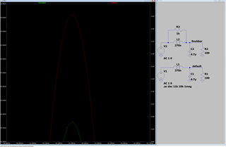
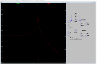
I am puzzled by an element of the filter design found in SNVA886: Reduce Conducted EMI in Automotive Buck Converter Applications. A 2k resistor (RF2) appears in parallel with the ferrite (LF2), and is attributed to "preventing filter stability issues."
Can you provide any further information on what these filter stability issues might be? I haven't been able to find a clear answer from searching online. Based on an LTSpice simulation of this I see only a difference of 0.5dB w/ 1MOhm load, 0.32dB w/ 100 Ohm load, and ~0dB with 1Ohm load.
It also seems odd to me because the LM62460RPHEVM which I have been using as one of my benchmarks in testing does not implement this. Your answer will be helpful for us to decide if we actually need a placeholder for this on our next rev of PCBs.

