This thread has been locked.

If you have a related question, please click the "Ask a related question" button in the top right corner. The newly created question will be automatically linked to this question.

TPS61230A: Audible Ringing in Circuit

Part Number: TPS61230A

Hello,

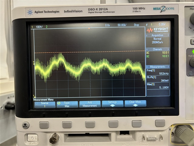
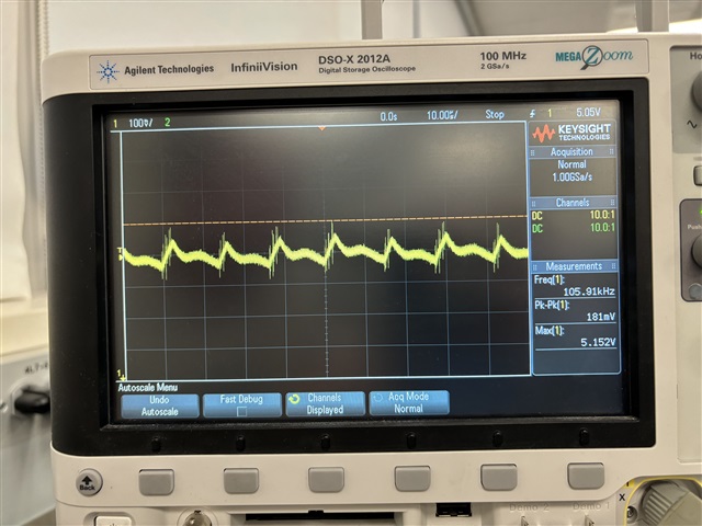
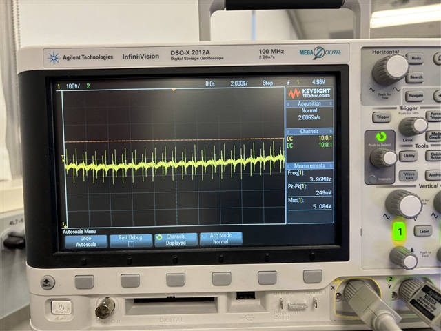
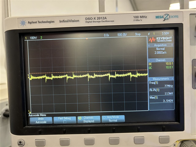
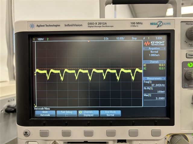
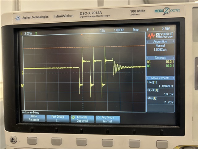
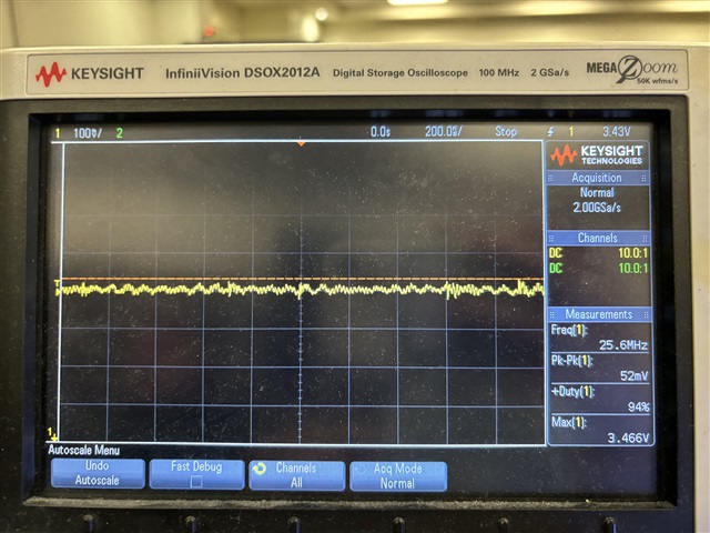
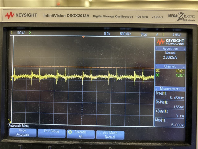
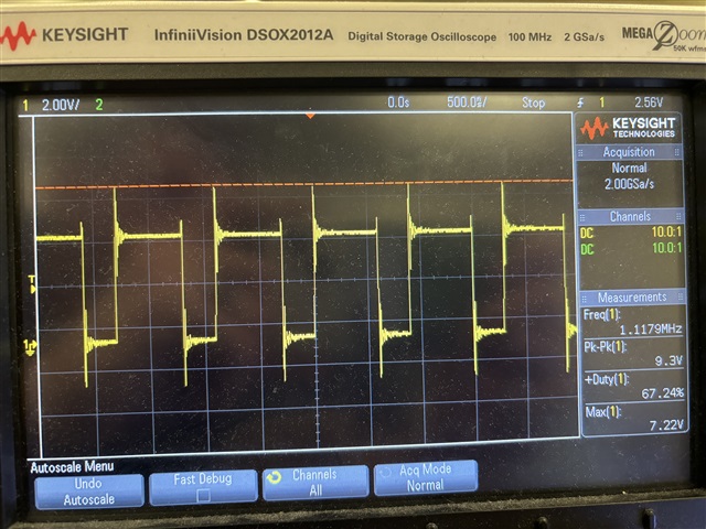
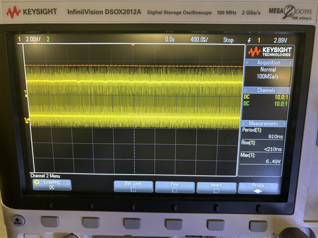
I am a student working on a project. I am using this part to boost a lipo battery to 5V. I am getting the functionality I want, but I am hearing some audible ringing that I believe is coming from the inductor (possibly the output capacitors?). The pitch increases as the current pulled from the output increases. I am assuming this is a sign of a fault in my design or layout, and I am hoping to get some assistance in debugging this issue. 

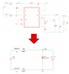
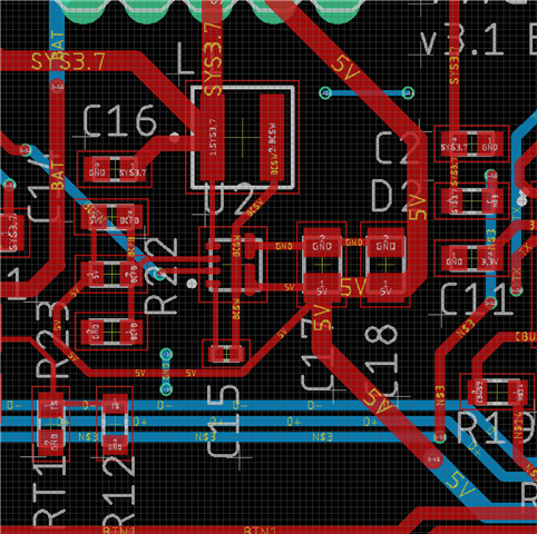
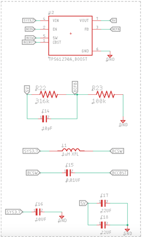
I have attached a screenshot of my schematic and my board layout of the boost portion of the board, as well as the components that I am using. Please let me know if I can provide any other information that might help us solve the issue. Any other feedback on the provided information is appreciated as well, as I would really like to improve my design skills. 

10uF Capacitor 0603 C1608X5R1A106K080AC
10pF Capacitor 0603 CC0603JRNPO9BN100
22uF Ceramic, 10V 0805 GRM21BR61A226ME44L
0.01uF Ceramic, 10V 0402 GRM155R61A103KA01D
1uH Shielded, Composite 1616 XAL4020-102MEC
316k .1W 0603 CRCW0603316KFKEA
100k .1W 0603 CRCW0603100KFKEA

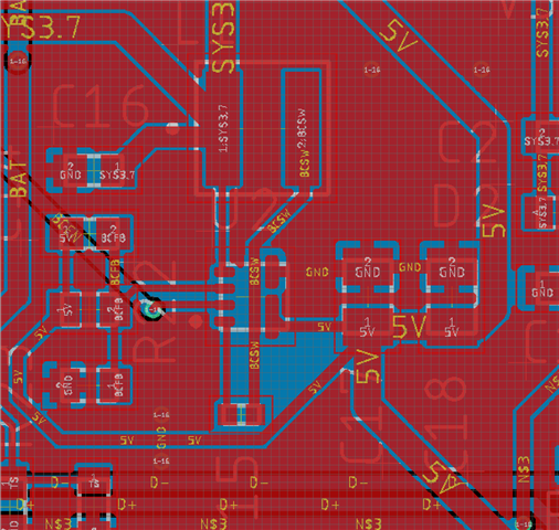
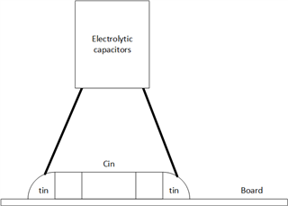
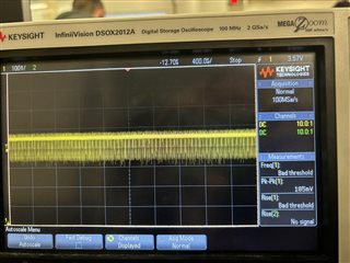
above photo to show ground planes 

  • Hi Emma,

    There are a lot of things in your layout that may causes some problem. But first let's eliminate other possible problems:

    Put extra bulk e-caps in parallel on your C16, remove C17 and try again:

    Catch waveform of the device if the ringing occurs: voltage on BCSW, voltage on 5V output, voltage on 3V7 input and inductor current if possible.(One at 500us/div, another zoom in until 4-5 switching cycle fulfills the screen)

    About layout:

    Please read this and try optimize it first. I'll help you review it when you finished.

    Best Regards,

    Travis

  • Hi Travis,

    Thank you for your reply! Here is what I have done:

    - I put a 22uF electrolytic capacitor in parallel with C16. No noticeable change in the ringing.

    - I removed C17, and again put a 22uF electrolytic capacitor in parallel with C16. Again, no noticeable change in the ringing. 

    I will have access to a oscilloscope tomorrow, so I will capture the waveforms then. 

    Thank you!

    Emma 

  • Hi Travis,

    I was able to get the waveform today. My apologies for having photos of the o-scope instead of the screen capture, I didn't have a flash drive to save them on. If there are any that you need in higher quality, let me know and I can redo them tomorrow. All of them were done with C17 removed. I repeated each capture both with the load attached and detached. Please let me know if there is anything else that I can provide that may be useful in diagnosing the issue. Thank you so much! 

    1. SYS3.7V with load detached

    2. SYS3.7V with load attached

    3. 5V with load detached

    4. 5V with load attached

    5. 5V with load detached (close up)

    6. 5V with load attached (close up)

    7. 3.7V light strip attached (close up)

    8. 3.7V load detached (close up)

    9. BCSW load detached

    10. BCSW load attached


  • Hi Emma,

    I'm sorry that I typed the wrong number. I meant remove the 10pF C14. C17 should not be removed.

    Also, as there's still a lot of ringing in the input, I recommend putting over 220uF electrolytic capacitor in parallel with C16. These electrolytic capacitors can be removed when the problems are solved. But for now, let's eliminated the ringing on the input and see if the ringing is caused by the controlling loop.

    Best Regards,

    Travis

  • No worries! I replaced C17 and removed C14. I also added a 470uF capacitor in parallel with C16.  

    These are plots with the load attached. There was still a small amount of audible ringing. 

    1. 3.7V

    2. 5V

    3. BCSW

  • Hi Emma,

    About the input capacitance & ESR:

    If parasite inductance on the input power rail is not carefully reduced in your layout, the parasite inductance will ring with the input capacitor. Add bulk capacitance or cin with big ESR will reduce this issue:

    About Feed forward capacitance C14:

    In most cases feed forward capacitors should be designed to place a zero on about 3*fc to 4-fc frequency range to provide a better phase margin near fc without affecting bandwidth. If the feed forward capacitance is too large and the zero is brought into the bandwidth, there'll be risks that the fc will be pushed to higher frequency and the system will be unstable

    Feedforward Capacitor Makes TPS61021A Boost Converter Fast and Stable (ti.com)

    About further actions:

    Audible ringing occurs at the frequency between 20-20kHz. So I need 400us/div time scale to judge whether the ringing is from the capacitor or the inductor.

    Also, your layout needs to be optimized, still.

    Best Regards.

    Travis

  • Hi Travis, did you mean to attach something in your first message for me to refer to for the layout so that I can optimize it? I will get back to you with the waveforms. Thanks!

  • Also, for the plots with the 400us/div time scale, are you looking for the 5V 3.7V and BCSW again?

  • Hi Emma,

    Sorry that I missed the link:

    TPS61022 and TPS61023 Boost Converters Layout Guidelines (ti.com)

    About the waveform, yes.

    Best Regards,

    Travis

  • Hi Travis, thank you! I will look over that document and update my layout. Here are the waveforms

    1. 3.7V

    2. 5V

    3. BCSW 

  • Hi Emma,

    The Waveform looks normal. Are you still hearing things from the boost under this condition?

    Also, let me review it when the layout is finished.

    Best Regards,

    Travis

  • My mistake, I think I took these with the load disconnected. I took them again with the load connected and I can hear the ringing from the boost. 

    I will send over the new layout when I am finished, I will work on it this weekend. 

    1. 3.7V

    2. 5V

    3. BCSW

  • Hi Emma,

    Seems that the input still rings. Are you still attaching the input 220uF? Also, I would like to know your load conditions & zoom in waveform 1us/div.

    Best Regards,

    Travis