Hi
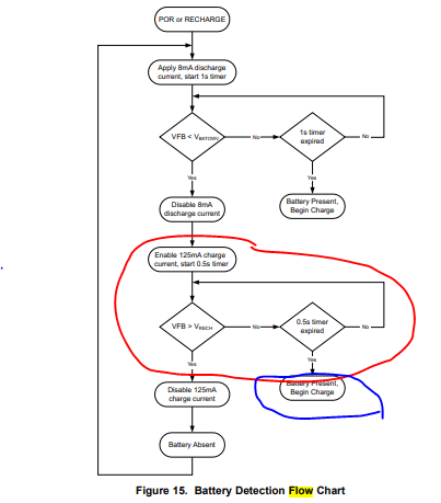
The customer design with BQ24171 to charge the 2 cells. They follow the datasheet 9.3.15 to do the battery detect test.
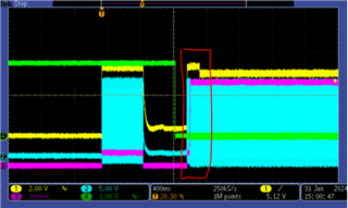
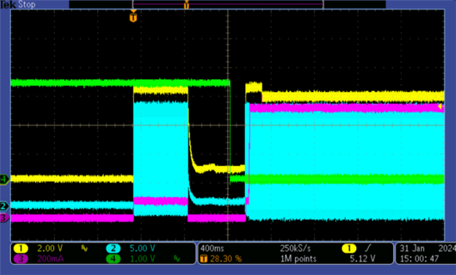
It was found that at the beginning of charging, charging stopped after maintaining a 100mA charging current for about 500ms, and the charging stop time was also about 500ms. During the period of stopping charging, the state changes from H to L. Then increase the charging current.
Attached the waveform.
Yellow: battery pack voltage
Blue: SW of charging IC
Red: charging current
Green: State of charging IC
Does it comply with the process in 9.3.15? The 125mA charging current is the red box part in flow? The 500ms to stop charging is Is it the switching time to start the official charging?
Please help check it.
Thanks
Star