This thread has been locked.

If you have a related question, please click the "Ask a related question" button in the top right corner. The newly created question will be automatically linked to this question.

TPS61040: EMI/EMC testing cases

Part Number: TPS61040

Hi 

I am using following part from TI
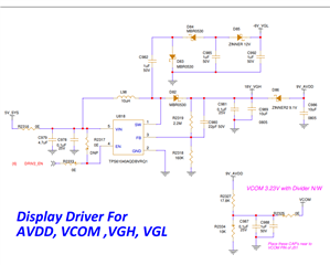
TPS61040AQDBVRQ1

I am using this part in my design for the display powering section, while testing in the RI test I am getting display flickering at 310MHz.

and one more thing less than 310MHz & more than 310MHz i am not getting any flickering but only in 310MHz i am getting that issue. 

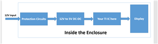
Actual what is the test case is we have closed the enclosure means the EV cluster, in that we are using one display that requires your driver to give some voltages, Like AVDD, VCOM, VGH, and VGL. Then we are connected with the Vehicle and do the EMI/EMC RI testing, that time 310MHz the display gets a jitter or Flickering issue, If the RF signal (RI) is less the 310MHz or more than 310MHz we are not getting any issue,
I hope you got my point, please provide me a solution. 
For your reference, i am attaching the video also please refer it along with the schematic.
  • Hello karthik kb,

    Thank you for using E2E. I am sorry, but the expert for this device is out of the office for this week.

    RI test means you inject the RF signal into the power line or where do you inject it?

    Could you take measurements of the input and output voltages while you inject the RF signal? I wonder which signal is falling out of regulation causing the flickering.

    Best regards,
    Brigitte

  • Hi Brigitte,

    Thanks for your replay, we have closed enclosures inside that display & PCB is there, On the PCB this driver is there from TI and from PCB to Display connected via FPC cable,

    The test case is we have connected this device to automotive vehicle while doing vehicle EMI/EMC testing we are injecting the RF frequency from 20Mhz to 2GHz that time at 310MHz we are facing this issue.

    Thanks & Regards

    Karthik 

  • Hello karthik,

    If you have the ability to measure the input voltage to the enclosure, please check if there is a high amplitude of fluctuation at this frequency. On the other hand, I think a ferrite bead which has a low impedance at 310 MHz might help if you add it to the input of the module.

    Best regards,
    Brigitte

  • Hi Brigitte,

    Please find the attached file for your review, is really input supply will affect on your TI driver as per bellow image.

    Due to DCDC and protection circuits it may not affect more on the Display. 

    Regards

    Karthik

  • Hello Karthik,

    This depends if the protection circuit and the 12V to 5V DC/DC are effectively filtering the 310MHz signal or not. If the power supply rejection ratio at this frequency is low, 310MHz can pass through to the display.

    On the other side, are you sure that the issue is caused by the power connected to the display or is the 310MHz signal possibly influencing the display through the controller that drives the signals you display on the screen?

    Best regards,
    Brigitte

  • Hi Brigitte,

    Good Day

    We have tried with changing clock frequency of our display. Our flickering issue got resolved the RI test also passed. And Thanks for your support

    Thanks & Regards

    Karthik KB 

  • Hi Karthik,

    I'm glad to hear the good news that the issues has been resolved. 

    Thanks for Brigitte's great support as well.

    I'll close this E2E thread. You can still reply here if you see any further concerns.

    Regards

    Lei