This thread has been locked.

If you have a related question, please click the "Ask a related question" button in the top right corner. The newly created question will be automatically linked to this question.

LM5164-Q1: Converter output is 17V instead of 15V

Part Number: LM5164-Q1
Other Parts Discussed in Thread: LM5164,

Hi team,

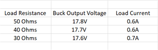
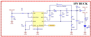
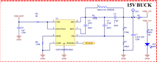
I have designed 48V to 15V converter by using LM5164-Q1 IC, the converter output is 17V instead of 15V, please let me know where is the problem with passive components or LM5164 IC I couldn't understand,  please find the attachment for your reference.

Thanks& Regards,

Jayanthi.

  • Hi Jayanthi,

    I suspect the part may be running at light-load. In that case, output may be overcharged, and a pulse will be issued when the feedback pin voltage dips below 1.2V. I suggest increasing the load to see if this resolves the issue. 

    If not, can you provide your operating (input and output load)?

    Thanks,

    Richard

  • Hi Team,

    As per your suggestion i have given high- load to the buck converter (LM5164-Q1) and i have observed below mentioned output voltage. my problem was not solved, Could you please give me any  solution for this problem.

    Feedback Pin voltage is 1.3V.

    Thanks,

    jayanthi.

  • Hi Jayanthi,

    This is odd, feedback pin internal reference should be 1.2V. Can you replace the IC and check with another unit and see if the issue follows? 

    Thanks,

    Richard

  • Hi team,

    I have already replace the LM5164 IC, but the results are same as previous IC, New LM5164 IC output voltage also shows 17V instead of 15V. Please check once my design Schematics, is there any changes are needed for selecting the passive components. 

    please find the attachment for your reference. please give me any solution for this problem.

    Thanks,

    jayanthi.

  • Hi Jayanthi,

    The schematic looks ok. Can you confirm that the layout matches the layout guideline in section 10.2 of the DS? Is the feedback trace far away from the switching node?

    Can you take a waveform of VOUT, VIN, SW (a few cycles), and FB in steady state, just so we can confirm normal steady-state behavior? 

    Additionally, it looks like there was another thread recently that discusses a similar issue. Can you use the calculator here and adjust the values of R1, C3, and C5? The alternative post suggests the following values: R1=787k, C3=2200pF, and C5=56pF

    https://www.ti.com/tool/LM5163-LM5164DESIGN-CALC#downloads 

    Thanks,

    Richard