This thread has been locked.

If you have a related question, please click the "Ask a related question" button in the top right corner. The newly created question will be automatically linked to this question.

USB-C-PD-DUO-EVM: Problem to flash USB-C-PD-DUO-EVM board

Part Number: USB-C-PD-DUO-EVM
Other Parts Discussed in Thread: TIDA-050012

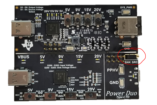
I have problem to program USB-C-PD-DUO-EVM board( the SPI flash on TIDA-050012 was erased previously).

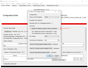
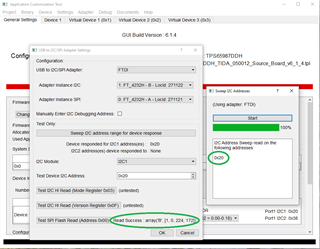
I was able to load project using Application Customization tool through the following step. New project --> TPS65987DDH--> TIDA-050012 Source board.

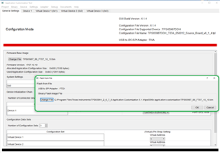
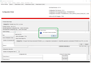
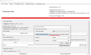
tried to program the flash using "Flash Project to Flash (SPI)". it showed device failed to verification.

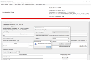
Tried "Flash read" the binary file from another good USB-C-PD-DUO-EVM board. The binary file TIDA-050012 for was generated successfully. However, when use the binary file to program the erased TIDA-050012 board, it always show "SPI Flash to Device failed verification".

Please help.


  • Hi Michael, 

    Can you help check and make sure the jumper circled in the picture below is set to SRC? This connects the FTDI on the SINK side of the board to the SPI flash on the SOURCE board. 

    When programming, make sure the board is powered through the barrel jack as well, otherwise the flashing process will not succeed. If it still fails try checking the Adapter page setting in the Application Customization Tool and make sure the device is detected by sweeping. 

    Let me know if this works or not!

    Thanks and Regards,

    Raymond Lin

  • Hi Raymond,

    Thank you for the help. Yes, J202 was moved to SRC side when flashing the source board. 

    Today I was able to flash the source board successfully. However, the board does not work after flashing. See screen shot below.


  • Hi Raymond,

    Thank you for the help. Yes, J202 was moved to SRC side when flashing the source board. 

    Today I was able to flash the source board successfully. However, the board does not work after flashing. See screen shot below.

    After flash the SPI flash, I removed the micro-USB cable, moved J202 to sink side, installed USB cable between source and sink board, and powered the board, the board did not work. Note the same setup works on another board which has never been reflashes.

    I tried to flash the board using "flash from current project" option. But it showed "invalid region pointers read" error.

    The board did not work using this method either. 

    Thanks,

    Michael

  • Hi Michael, 

    From the screenshot you sent it looks like the flashing was successful, what was the behavior of the source board when you plug it into the sink board? 

    Thanks and Regards,

    Raymond Lin

  • Hi Raymond,

    As I mentioned in previous message, it did not work. No VBUS power output when sink board is attached. I believe the SPI flash was not programmed correctly. If you check the images I provided using "flash from current project" option. It showed "invalid region pointers read" error. I doubt if the pointers (offset) were set properly. 

    Because I have both working work and non-working board, I will dump the SPI flash from both board and compare the files.

    Thanks,

    Michael

  • Hi Raymond,

    Today I connected the working board to the computer. I was able to read the region offset which is 0x2000 for region 0 and 0x6000 for region 1. After that I plug the non-working board back and use "flash from current project" to program the SPI flash. Instead using default setting 0x2000 and 0x20000, I manually adjusted the offset to "0x2000 and 0x6000" and clicked on OK. After finished flashing, the board worked!

    The bin file provided is not full size image. There is no region offset provided in the bin file. When flash from bin file, the APP read offset from existing SPI flash. However, because did "flash erase" on this board previously, the APP could not get offset information from the flash. so the default setting "0x2000 and 0x20000" is used which is wrong. 

    Also, I found a schematics error which results unstable SPI interface. That's why I and many people had problem programming sour SPI previously. see picture blow.

    U201 pin does not have pull up resistor. The net attached to R205 should be SPI_CSZ_SINK which is U201 pin 1. When the board is powered initially, the sink board does not have power. However, the power from source board leaks to sink board and make U201 active. If CS pin is not pulled to high, the voltage level is unstable and could be o. the pin 2  SPI_MISO hold the SPI bus in this case and source board could not boot up. The work around is move J202 jumper to SINK side and provide a pull up to U201. This is clearly stated in USB-C-PD-DUO-EVM user manual.  However, when program the source board, we have to move the jumper to source side. then U201 CS pin becomes floating. That is why many people got intermediate problem to program the source board.  The I2C bus is only used for debugging not programming SPI flash.

    I also reworked the EVM board by adding a pullup resistor to U201 pin 1.  Now the board works regardless the jumper position of J202. It works great when jumper is removed or moved to source side. Also, with this rework, I no longer see flashing SPI flash fail.

    Regards.