This thread has been locked.

If you have a related question, please click the "Ask a related question" button in the top right corner. The newly created question will be automatically linked to this question.

UCC21750QDWEVM-025: Eval Board and mosfet damage during Short circuit test

Part Number: UCC21750QDWEVM-025
Other Parts Discussed in Thread: UCC21750

Hi ,

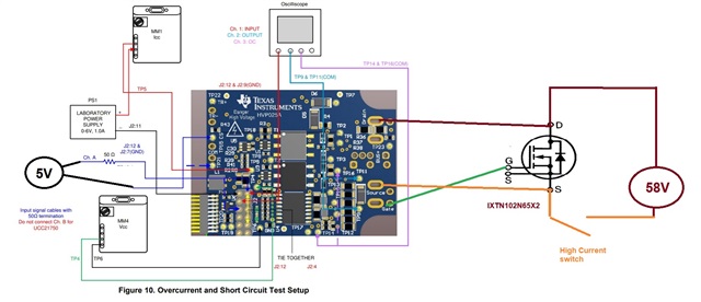
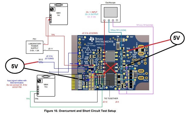
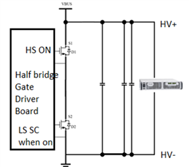
We are developing application to detect short circuit for lithium battery, to cut off the MOSFET immediately in event of short circuit. The MOSFET we are using is the IXTN102N65X2 with 30 mOhms of Rds On - Drain-Source Resistance.

As shown in the circuit below, we follow the short circuit sluubx2b.pdf instructions but replace the Function gen with a fix 5V source at channel A to turn on the MOSFET (voltage measure across the gate and source is 17V). We use high current SW to simulate short circuit, but the moment the SW is turn on, the MOSFET blown up and the UCC21750 chip damage. The Rdy LED turn off but the FLT Led remain on, the voltage across the  gate and source remain at 15V, even with the 5V at channel A remove. 

We remove the UCC21750 but replace with UCC21756, voltage measure across the gate and source become -0.5V. Measure the voltage across COM and VEE is 0.5V.  Remove the UCC21756 and measure the COM and VEE is around 4.5V, solder another UCC21756 and the COM and VEE become -0.5V. Not sure if other components could have have damage

Hope to get some advise how we can solve these issues. Thank you

Rgds,

YK


  • Just a correction on the figure above , the Gnd connection of the 5V signal is connect to J2:7 and not to CS pin. 

    An update: 

    We remove the Transformer at T2 and pump in -5V as we suspect the DC-DC for Vee might hv some damage.

    With the new UCC21756,  we remove the 5V at the input and both Rdy LED and FLT Led lit up on power up, there is -5V measure across the Gate and Source but the moment we place back 5V, only the Rdy LED lit up and FLT Led extinguish. -5V still remain at the gate and source.  


  • Hi Toh,

    Thanks for all the detailed message on your test setup and your debug approach to narrow down the issue. Good to hear that you got the setup working.

    When INP=H, the DESAT circuit will charge the blanking capacitor and will trigger FLT. Its expected behavior. When not connecting FET, to avoid FLT, please short DESAT to COM. Hope it helps.

    Thnaks

    Sasi

  • Hi Sasi, 

    Thank you for reply, you are right, after we connect to FET, we are able to get the setup to work again.

    Unfortunately when we repeat the short circuit test, the Mosfet blown up and the new UCC21756 fried as well.

    Can you advise how to solve this issue?

    Thank you

    Rgds,

    YK


  • Looks like the MOSFET breaking first (may be due to high di/dt with large inductance in the path causing over voltage) and then breaking the Gate driver as well as Gate is exposed to high voltage.

    Can you exercise SC by having high voltage source across bulk capacitance and then turn high side first and then low side. Or (in reverse order).

  • Hi Sasi, 

    Our test for Short Circuit is as shown in the figure above. 

    First we switch on the MOSFET 

    Next, we switch on the mechanical switch to create a short circuit. 

    But it still blow the MOSFET. 

    Any idea how to prevent this? 
    By increasing the Resistance of R4? from 1K to more for a faster reaction time?

  • Hi Raymond,

    Thanks for your simplified block diagram setup image.

    it is possible that the di/dt is increased at faster rate, depending upon how fast that switch is closing. can you control the speed of the 2nd switch closing.

    If not, can you try RC snubber across it to slow down the switching. Another thing to consider is minimizing the overall inductance in the high current path to minimize the overshoot voltage.

    Hope it helps.

  • Hi Sasi, 

    The whole purpose of the test is to simulate an external short circuit by the user, hence the step 2 of the switch is simulating it. 

    The objective is to prevent MOSFET from blowing up. 

    Regarding your solution, RC Snubber across which component? Is it over the MOSFET? 

    How to get the correct value for the RC? 
    Increasing the R4 value of to DSAT doesn’t help? 

  • Hi Raymond,

    Can you please share the voltage at the Gate, and voltage across FET when you turn the external switch on?

    I am thinking that the external switch is turning on much faster and hence it cases faster di/dt and causing overvoltage across the module. Its based on the assumption. So recommended for RC across the external switch. But let us first confirm it before we plan for it. 

    If you can share the scope capture, it will help us to narrow down the root cause.

    R4 can only help to minimize the current conduction from DESAT pin to the FET and to reduce Desat detection threshold- it can not help if there is overshoot present already on the 1st switch. That is what we need to check.

    UCC217xx XL Calculator Tool - helps to calculate required desat threshold needed for your power module.

  • Hi Sasi, 

    The whole purpose of this test is to simulate someone accidentally shorted the battery. So I dont think we can add RC across the external switch. 
    We thought this driver should response fast enough to prevent blowing of MOSFET. 

    Hence, is there any way for us to design in this driver board to prevent MOSFET from blowing? 

  • Hi Raymond,

    What is the expected protection DESAT threshold voltage for the power switch? Have you updated the desat circuit to be triggered within that threshold voltage?UCC217xx XL Calculator Tool - Please use this calculator to define the threshold voltage and detection time as required for the switch in your system.

    Is it possible to share the waveforms what we have requested? Without it, it will be very hard to explain what is causing the failure?

  • Hi Sasi, 

    1. How do we get the DESAT threshold voltage for the power switch? 
    we are using IXFN170N65X2
    https://docs.rs-online.com/bc3b/0900766b815e9d32.pdf

    2. We test using the default value of your EVM board. 1k Ohm

    3. We are trying to get the waveform of 
    Vgs & Vds. 

  • Hi Raymond, 

    Sasi is currently out of office so I can help with the inquiries in the meantime. 

    The DESAT threshold voltage is highly dependent on your system; it cannot be too low, or DESAT would false trigger; it also cannot be too high, since the power switch might overcurrent before soft turn-off initiates. 

    I would recommend measuring the Vds voltage under the normal operating condition of the system. Your DESAT threshold should be higher than that, so iteratively set the DESAT threshold and test the system, until you find a sweet spot with no false triggering and good protection. 

    Like Sasi said, waveform would be very helpful for us to help with debugging the problem, so please send the waveforms over when you have a chance. Also note that UCC21756 has a different DESAT threshold (5V) compared to UCC21750 (9V), so make sure to fill in the correct values when you're using the calculator tool. 

    Thanks, 

    Vivian