This thread has been locked.

If you have a related question, please click the "Ask a related question" button in the top right corner. The newly created question will be automatically linked to this question.

TPS55288-Q1: Switching Voltage Regulators 36-V, 16-A buck-boost converter with I2C control, AEC-Q100 qualified 26-VQFN-HR -40 to 150

Part Number: TPS55288-Q1
Other Parts Discussed in Thread: LM51772, LM5171, LM5117, LM5177, LM5171-Q1, BQ77PL900, BQ78PL114, LM5171EVM-BIDIR

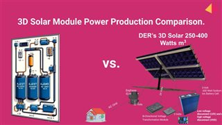
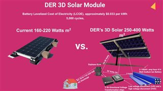
I need to design a board that can connect 14 of these TPS55288-Q1 devices to replace the Vicor VTMs, as we need to step up the voltage from 3 volts to 22 volts. This tricks the grid-forming enphase microinverter into discharging the High-Temp Sodium Ion Battery Cell, which can charge and discharge at 85°C and -70°C. We also need to step down the solar module voltage, which ranges from 24-36 volts, to charge the 3-volt battery. We would program the device to charge the battery early in the morning when the voltage is low and discharge it when the sun goes down. We want the electronics to last 20 years like a solar module and battery cell.

  • Hi Daniel,

    Thanks for reaching out. 

    From my understanding, the device you need is the bidirectional dc-dc converter, which operates at Boost mode with 3Vin to 22Vout, and operated at Buck mode with 24-36Vin to 3Vout, right? What is the load current for each mode? Do you have any block diagram for better understanding?

    BRs,

    Bryce

  • I dont have a block diagram. I was thinking 20 of these devices connected in parallel which would be a max of about 120 amps. 80 Amps would be the go to current.

  • Hi Daniel,

    For this power level, I think Buck-boost controller is more suitable here. Less device in parallel will be required. I will loop our Buck-boost controller experts for better recommendations.

    BRs,

    Bryce

  • Hi Daniel,

    i am also not sure if I understood the operation mode (bidirectional) but i would assume:

    one direction:  24-36V   ->   3V

    other direction:  22V    <-     3V

    On which side would the 120A then appear?

    I think the LM51772 would be a well fitting device based on my understanding so far.

    Best regards,

     Stefan

  • Apologies for the delay Stefan. Your assertions are correct "

    one direction:  24-36V   ->   3V

    other direction:  22V    <-     3V"

    The Sodium Ion Cell 3 nominal volts but the cell could reach 2.25-2.5 volts when the battery is at 15% state of charge. That device you recommend.  We started this Techstars today. Any new suggestions?

  • Im reffering to the DC Side. Dont we need to add MOSFETS to that board? I dont he how we can get 80-100 amps at 3 volts for charging

  • Hi Daniel,

    the LM51772 is not able to operate down to 2.25V

    Please check the LM5171 - this should fit better as you only have Buck in one and Boost in the other direction.

    This device also can be used for Mulitphase which might be required for the high currents you are targeting.

    I am not sure what you mean with: "Don't we need to add MOSFETS to that board" - you for sure need MOSFETs for the DCDC.

    Best regards,

     Stefan

  • When you say Multi-Phase do you mean 2 110 volt legs? The Enphase Microinverter has two 110 volt legs that can combine for 220 volts to start High Power Applicances like AC's. When Chat GPT 4 read the datasheet I asked what is the max amps and 3 volts and 22 volts and it said "Depends on the MOSFETS you add to the board"  Next step would be to build this board where we only push the MOSFETS to a certain level of peak ability like 60% so it lasts 25 years! Is there a way to make it last 25 years on the back of the solar module with a battery that will cycle 9000 times over 24.66 years? Keep in mind the battery will charge in the am when temps are not very hot. Then everyday from 11am-6PM its going to get up to 65C under the solar module in say Arizona and California when its 105 F. We need to build the device to last that long so I can show TVA the largest power company in USA that LCOE of $.03 cents per kWh over the lifetime of the battery cell.

  • I started this Techstars this week. TVA, UT, and Oak Ridge National Lab are partners.  www.techstars.com/.../industries-of-the-future

  • That new datasheet for the LM5117 says 3 volts minimum. Are you sure it can reach 2.5-2.75 volts? We need to do a voltage curve on the sodium ion cell so I am guessing on that but if the nominal voltage on the cell is 3 volts it could in theory go to 2.5 volts

  • Hi Daniel,

    just to ensure: which device you are referring to:

    LM5177

    LM5117

    LM5171

    All of them do exist.

    What do you mean when asiking: Are you sure it can reach 2.5-2.75 volts? 

    Best regards, 

     Stefan

  •  LM5171. It says in the datasheet 3 volts min. Are cell could go down to 2.5-2.7 volts when the battery is at like 3% State of Charge in the AM before the solar module starts charging the battery. We need to be able to push 80 amp continuously from the battery when discharging it. Can you help me figure out the amount of MOSFETS needed in the LM5171 for our application with a idea on price? Can this device last 20-25 years and cycle 6000-9000 times? 

  • [deleted]
  • Can you give me a idea on the cost differnece at 3 volts vs 6 volts? This is why I dont want to connect in series parallel! "

    1. Series Connection: When you connect batteries in series, you increase the voltage while keeping the capacity (mAh) the same. In your case, connecting two 3V batteries in series would give you a total voltage of 6V. This might be suitable for certain applications that require higher voltage, but it does come with some drawbacks. One issue is that if one battery fails, it can affect the whole circuit, potentially reducing reliability. Additionally, if the batteries have different capacities or states of charge, it can lead to imbalances and decrease overall performance and lifespan.

    2. Parallel Connection: Parallel connection involves connecting batteries together to increase the capacity while maintaining the voltage. In your case, connecting two 3V batteries in parallel would give you a total capacity of the batteries while keeping the voltage at 3V. This configuration can provide more power for longer durations, but it's crucial to use identical batteries to avoid imbalances. One advantage of parallel connections is that if one battery fails, the others can still operate, providing redundancy and potentially extending the lifespan of the system."

  • Hi Daniel,

    accidentally delete above answer - restored here again.

    LM5171 LV port can go down to 1V in boost mode. So, it is OK for 2.5-2.7 volts.

    But, if possible, use a few batteries in series would result in better efficiency and lower cost.

    It would be much easier and cheaper to handle 6V/60A or 12V/30A than 3V/120A.

    Best Regards,

    Feng Ji

  • If we do series parallel we need a BMS for balancing the 600 Watt Sodium Ion Cells. The BMS only lasts 5-7 years.

  • Im willing to pay more to have it operate at 3 volts in parrallel 

  • Im open to your 6 volt request but hesitant. Our cell at 5% state of charge is 2 volts and at 90% is 4 volts

  • Hi Daniel,

    6V/60A will result in better efficiency and lower cost.

    Let's say this way, with LM5171, you can achieve 6V/60A with 1 pcs LM5171; But you are suggested to use 2 pcs LM5171 for 3V/120A.

    The total cost of 3V/120A will be almost 2 time.

    Best Regards,

    Feng Ji

  • What is the cost per board? Can the board balance the battery cells for charging? If not using two boards with thicker cable would work better to keep it caveman.

  • Can we add Bleeding Resistors? If so we could use just 1 board with the 2 Cells at 6 volts based of the Voltage Curves for High and Low Voltage Cutoff.

    How Passive Balancing Works

    • Bleeding Resistors: In passive balancing, each cell in the battery pack is connected to a resistor (the bleeding resistor). These resistors are usually connected across the cell terminals through a switch (which can be a simple MOSFET) that is controlled by a voltage monitoring circuit.
    • Voltage Monitoring: The system continuously or periodically monitors the voltage of each cell. When a cell's voltage exceeds a predetermined threshold—indicating it is more fully charged than desired—the switch connecting it to its bleeding resistor is closed.
    • Dissipating Excess Charge: With the switch closed, the excess charge from the cell is dissipated as heat through the resistor. This process gradually reduces the cell's voltage to a level closer to its peers, achieving balance across the pack.

    Using Voltage Curves for Balancing

    The LM5171-Q1, as a sophisticated power management IC, has capabilities that could potentially be leveraged for a rudimentary form of balancing between two cells by monitoring voltage levels and managing power transfer accordingly. This could involve:

    • High and Low Voltage Cut-off: Implementing protections based on high and low voltage thresholds to prevent overcharging or over-discharging of the cells. This method can help ensure that cells remain within safe operating limits.
    • Voltage Monitoring: By observing the voltage levels of each cell, the controller can infer their relative states of charge, transferring power to or from a cell when its voltage deviates from a set range. This is a basic form of balancing, assuming the cells' voltage characteristics are well understood and consistent.
  • I would need to combine a passive cell balancer bq77PL900 or a active cell balancer bq78PL114. Please keep in mind we want these components to 8000-10,000 Battery Cycles over 20-25 years. By following your advice by combining two 3 volts sodium ion cells in series parrallel that might be the set up. What do you think? Whats the price for bq77PL8900 and LM5171

    bq77PL900 or a bq78PL114

    design a system where the bq77PL900 (used for passive cell balancing within a battery pack) works in conjunction with the LM5171 (which manages power conversion) to optimize battery discharge and then step up the voltage for AC conversion by an Enphase microinverter. Here’s a high-level overview of how this system could be structured:

    Step 1: Passive Cell Balancing with bq77PL900

    • The bq77PL900 can monitor individual cell voltages within your battery pack and engage passive balancing to ensure all cells are kept within a similar voltage range. This process involves dissipating excess energy from higher-charged cells as heat, thus preventing any single cell from becoming overcharged and promoting longevity and efficiency of the battery pack.
    • It's worth noting that passive balancing is more about maintaining cell health and balance rather than actively discharging the battery pack for energy utilization.

    Step 2: Voltage Step-Up with LM5171

    • Once the cells are balanced and the battery is discharging, the LM5171 can take the output from the battery pack and step it up to the required 22 volts needed by the Enphase microinverter.
    • The LM5171 is designed for high-efficiency power conversion and can handle the bidirectional transfer of power, although in this scenario, you are primarily concerned with stepping up the voltage from the battery pack for AC inversion.

    Step 3: AC Conversion and Grid Integration

    • The stepped-up DC voltage (22 volts) provided by the LM5171 is then converted into AC by the Enphase microinverter, which can then be synchronized and fed into the grid.
    • Microinverters like those from Enphase are designed to convert DC to AC at a very high efficiency, and they include the necessary circuitry to ensure that the AC output is in phase and meets the grid's voltage and frequency standards.

    Considerations:

    • System Integration: This approach requires careful system integration to ensure that the operations of the bq77PL900 and the LM5171 are well-coordinated. While the bq77PL900 will primarily be active during the charging or when balance is needed, the LM5171's operation during battery discharge needs to be efficiently managed.
  • Hi Daniel,

    You need to determine to use 3V or 6V.

    You can post a new thread if you are considering the cell balancer.

    You can contact TI local sales office for the price.

    Best Regards,

    Feng Ji

  •    I'm in Techstars TN, Industries of Future. Oak RIdge National Lab needs the XLM5171QPHPRQ1 Chips and Evaluation Module  LM5171 Evaluaton Module for testing. it says they are not in stock. They were in stock before. Did someone buy them all? Can you send a sample to Oak Ridge National Lab?

  • Hi Daniel,

    Can you contact a TI local sales office for samples?

    Best Regards,

    Feng Ji

  •  Texas Instruments declined my sample request, suggesting I purchase the components instead. The challenge is sourcing an evaluation board suitable for the LM5171-Q1 MOSFET chips, akin to the LM5171EVM-BIDIR Evaluation Module, which has a minimum threshold of 6 volts. We need an alternative evaluation board that can accommodate voltages as low as 2 volts, where we can integrate the LM5171-Q1 MOSFET Chips. Can you help identify an appropriate evaluation board for our requirements? Oak RIdge National Lab will help with the testing as I am in Techstars TN Industries of the Future.

  • Texas Instruments declined my sample request, suggesting I purchase the components instead. The challenge is sourcing an evaluation board suitable for the LM5171-Q1 MOSFET chips, akin to the LM5171EVM-BIDIR Evaluation Module, which has a minimum threshold of 6 volts. We need an alternative evaluation board that can accommodate voltages as low as 2 volts, where we can integrate the LM5171-Q1 MOSFET Chips. Can you help identify an appropriate evaluation board for our requirements? Oak RIdge National Lab will help with the testing as I am in Techstars TN Industries of the Future.

  •  LM5171 Evaluation Module only goes to 6 volts!! Any other suggestions?

  • Hi Daniel,

    LM5171 Evaluation Module can only go to 6V because of the

    • UVLO setting
    • Aux power supply UVLO setting

    You may need to do some modification or use external aux power supply for 2V operation.

    Best Regards,

    Feng Ji