This thread has been locked.

If you have a related question, please click the "Ask a related question" button in the top right corner. The newly created question will be automatically linked to this question.

TPS2116EVM: TPS2116EVM Voltage Droop when switching from Vin1 to Vin2

Part Number: TPS2116EVM
Other Parts Discussed in Thread: TPS2116

 Hi all, 

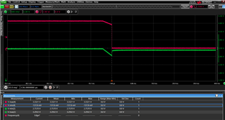
As shown on the right, Ch2 is Vout & Ch4 is ST. The voltage droop reaches to 2.75V from 3.3V supplies. It should be noted that Both Vin1 & Vin2 are 3.3v. The load used is the on-board 10ohm resistor. Furthermore, we've also used constant-resistance load varying from 50-10 ohms. The issue still persists. 

Could you please advise? We've tested for all three priority mode voltages (1.8, 3.3, 5). They all show 15%-20% droop. 

Yours, 

Ibrahim. 

  • Hi Ibrahim.,

    Welcome to e2e!

    What state is the MODE pin in? Please ensure that it is high, as that will put the device into priority mode. And, you will want to change the top resistor of the PR1 resistor divider to program what voltage you want the device to switch over at. Currently, with the 3.3V jumper, the device will switch over when VIN1 = 2.9V. If you want it to switch over earlier, for example at 3.1V, you would want a 10.5kOhm resistor on top.

    Alternatively, if you want to use whichever input is greater, then you can connect MODE to GND.

    Also, do you have any of the output capacitors connected? If you don't have the 10uF or 100uF caps connected, I believe that that is where the extra voltage dip is coming from.

    Does that work?

    Thanks,

    Patrick

  • Hi Patrick, 

    Appreciate the prompt feedback. All good now! 

    Another inquiry, the TPS2116 consumes around 82uA while only Vin2 is connected. The pullup resistor on ST is 1.5MOhm. We couldn't pinpoint where this excess current is going to? According to our calculations & referencing the datasheet, it should be sub 10uA. 

    Yours, 

    Ibrahim. 

  • Hi Ibrahim,

    Great!

    The device itself should only consume 1.32uA Iq + 2.2uA ST current - a few places that extra current could be introduced is if there is a small but nonzero load connected, if you are using electrolytic caps that have high leakage on the input/output, or if you have scope probes connected while measuring (maybe 2 probes with 100kOhm resistance?)

    Does it looks like any of these conditions could apply to your setup?

    Thanks,

    Patrick

  • Truly appreciated. 

    This has resolved my issue. Now the current is within spec, 3.4uA. 

    Thanks!

    Ibrahim.