This thread has been locked.

If you have a related question, please click the "Ask a related question" button in the top right corner. The newly created question will be automatically linked to this question.

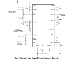
TPSM64406: SYNC Pin Strapping For Delayed Application of External Sync Clock

Part Number: TPSM64406

I would like to Sync the TPSM64406 to an external clock in my system; however, the desired external sync clock will not be available until a later time after the system (i.e and the TPSM64406 power supply) is up and running.

The applied external clock will be high-Z (floating) until the system is able to provide it.

Q1).  For what mode (FPWM = H; AUTO =L) should the SYNC pin be strapped in this situation?

Q2).  What is the recommended resistor value to pull the SYNC pin either high (for FPWM) or low (for AUTO)?  This pull-up/down resistor value needs to be large enough to allow the SYNC pin be over-driven by an external clock driver/buffer and still meet the vin_h/vin_l requirements for the SYNC feature.

Please advise as to MODE and RESISTOR strapping values?

Thanks,

M

  • Hi M,

    The SYNC pin should have a resistor to GND, so AUTO. I would recommend a starting value of 1kOHm.

    For sync, you just need to make sure the pulses are longer than Tpulse_H and Tpulse_L, as well as the amplitude meets the requirement. This has more to do with the external clock amplitude instead of the resistor. The other thing to keep in mind is that the SYNC frequency should be close to the programmed RT frequency to make sure transients caused by switching frequencies are small.

    Thanks,

    Richard

  • Great!  This addresses my needs.  Thank you for the support.