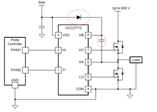
Most applications including power delivery for industrial and automotive utilizing a half-bridge gate driver use the bootstrap diode and boot capacitor to generate the high side driver bias. This is the simplest and most cost-effective method which works for most switching converters and half bridge power trains. An example with the boot diode and capacitor is shown below.
There are some applications which require very low frequency or long on time operation of the driver high side output, including up to DC operation. These applications can include DC high side switches and motor drive. In these cases, the bootstrap capacitor will be discharged over time due to the current required for the driver HB bias. In this case the HO output can not be maintained in the high state.
There are several options which can be used to bias the high side driver for these applications where the bootstrap method is not adequate.
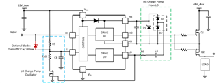
Charge pump for high side bias: Below is a method to use the low side driver of the half bridge driver to generate the high side bias through a charge pump capacitor. This method is explained in detail in the application note Implementing a battery disconnect switch using 100-V half bridge gate drivers. This approach is best suited to DC “on/off” operation or low frequency operation. This is due to the large capacitor value required for the charge pump capacitor.
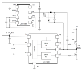
Transformer driver for isolated high side bias: There are simple IC solutions to provide the isolated high side bias for gate drivers. The UCC25800 is shown below which offers a wide VCC range. The UCC25800 information can be found at UCC25800-Q1 Ultra-low EMI transformer driver for isolated bias. The SN650x devices can also be used for the bias function. These bias solutions are suitable for high frequency half-bridge driver operation in a power converter. When using this method and the following two methods, please make sure the output voltage is higher than the VDD voltage to the driver IC, specifically if the gate driver has integrated boot diode. Also, do not rely solely on the capacitor close to the rectifier diode by the transformer winding. The gate driver still needs good bypass capacitors close to the gate driver IC.
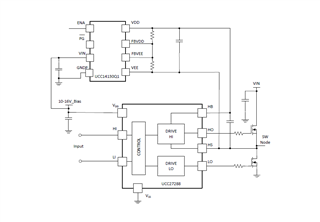
Isolated DC-DC module for isolated high side bias: There are small DC-DC modules available in SOP packages which can be used to provide the isolated high side bias for gate drivers. The UCC14130 is shown below which offers a wide VIN range. Information on the UCC14130 can be found at UCC14130-Q1 Automotive, 1.5W, 12-Vin to 15-Vin, 12-Vout to 15-Vout high-density isolated DC/DC module. There are a number of DC-DC modules available from TI. These bias solutions are suitable for high frequency half-bridge driver operation in a power converter.
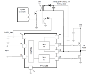
Add output winding to existing bias supply: Many designs have an existing bias supply for control and drive circuits. The floating high side bias can be supported by adding an extra output winding to the existing bias supply.