This thread has been locked.

If you have a related question, please click the "Ask a related question" button in the top right corner. The newly created question will be automatically linked to this question.

CSD19501KCS: MOTOR-DRIVE-FOC-FET-LOSS-CALC

Part Number: CSD19501KCS

Hello, TI team.

Thanks a lot to your team for sharing so many valuable design  reference documens.

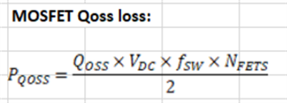
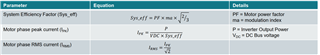
I am studying "MOTOR-DRIVE-FOC-FET-LOSS-CALC" for cross check MOSFET power loss.

Some calculation equations confuse me, could you share some related datasheet or manual for understanding them clearly?

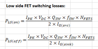
Such as: why the peak current is calculated by the following equation?

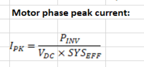
The calculation is based on current source drive, do I need to replace Ig(stc) with Ig(rms) for voltage source drive? How to define Nfets?

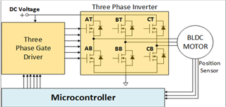
BTW, do you have any related simulation files regarding following block diagram?

Best regards 

Hailong.

  • Hailong,

    The person who did these tools is back in the office tomorrow and will be able to answer these questions

    Many thanks

    Chris Bull

  • Hello Hailong,

    Thanks for the inquiry. I got the equations from a systems engineer in the motor drive group. I have an email into him about the peak motor phase current calculation and will update you when I have more information. For the switching loss calculations, you need to use the gate drive current which is usually programmable on TI motor drive ICs that use external FETs. This is a static current used to charge and discharge the gate-source capacitance of the FET to turn it on and off. I'm not aware of any simulation files and I have also asked my colleague on the motor drive team.

    Best Regards,

    John Wallace

    TI FET Applications

  • Hello John,

    Thanks a lot for your kindly support.

    Look forward to your good news.

    Best Regards,

    Hailong.

  • Hi Hailong,

    Please see attached file for more detailed loss equations used by this tool. These are valid for 3-phase space vector PWM modulation.

    Thanks,

    John

    FOC FET loss equations.pdf

  • Hello, John

    Thanks a lot for your feedback.

    As I know, some equations are as below for FOC control(3-phase space vector PWM modulation)

    Modulation index: ma= π*Up/(2*Udc)

    Motor Input Power: P=3*Upk*Ipk*η3*COSα

    It couldn't get Ipk according to equations you shared. Maybe I didn't get them right.

    It seems Sys_eff is not equal to η1,and How to define Nfets?

    PF=COSα= Motor power factor

    P = Inverter Output Power

    η1=System Efficiency

    η2=Inverter Efficiency

    η3=Motor Efficiency

    Vdc = DC Bus voltage

    Ipk= Motor phase peak current

    Upk= Motor phase peak current

    Best Regards

    Hailong

  • Hi Hailong,

    Thanks for the follow up. NFETs = the number of FETs in parallel for each phase. Assumes an equal number of parallel FETs for top and bottom of each half bridge. I am going to send you a private message with my TI email address. I would like to move this discussion to regular email. This will allow me to loop in my colleague who has more expertise in motor drives. I'm the applications engineer responsible for TI discrete and power block FETs. I have limited experience with motor drives.

    Thanks,

    John

  • Hello, John

    Thanks a lot for your kindly support.

    Understood.

    Best Regards 

    Hailong.