This thread has been locked.

If you have a related question, please click the "Ask a related question" button in the top right corner. The newly created question will be automatically linked to this question.

UCC28065: Choke start/stop winding turns

Part Number: UCC28065
Other Parts Discussed in Thread: UCC28064EVM-004, UCC28061

Dear TI team,

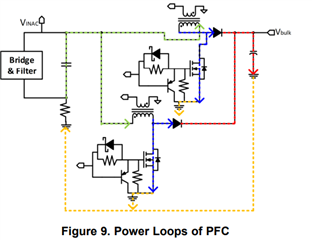
I have a question regarding the start/stop point of the winding choke.

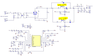
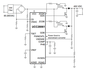
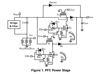
I have seen in the datasheet of the UCC28065, the start/stop winding turn of the choke is mentioned like this, the dot is actually placed at ZCD pins?
Furthermore, I would like to know what would be happened if the voltage coming from bridge rectifier connects to the starting point of the winding choke?
Is there any difference?
Could you explain that here?
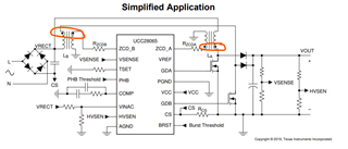

  • Hello Farhad,

    That is likely a typo in the datasheet. The UCC28064EVM-004 (https://www.ti.com/lit/ug/snvu587a/snvu587a.pdf) has the current sense transformers in the correct orientation.

    Regards,

    Jonathan Wong

  • Hi Jonathan,

    Ok thanks for the clarification,

    But still my question is unanswered!
    What is the difference if we place the transformer like datasheet?
    I would like to know the consequences?
    Do you have any reference that can explain this dot importance of the transformer in PFC controller 

  • Nevertheless, 

    I found in some datasheet and application notes, the drawing of the chokes are different,

    See below:

    1. Datasheet of the UCC28061


    2. Application Note (8 SLUA959–April 2019):


    3. Reference design (SLUU341B–DECEMBER 2008 – REVISED – MARCH 2009):


    I am totaly lost!

  • Hello Farhad,

    Correction 1: The transformers in question are not actually current sense transformers. A current sense transformer would be between the switch node and the MOSFET. The ZCD is actually connected to the boost inductor via an auxiliary winding.

    Correction 2: The dots DO matter and all the schematics you see above are correct. A misconception is that the dots represent the start/stop of the transformer. While typical, they are not the same. The dots ONLY represent the polarity of the transformer. As long as the dots are consistent with the direction of the boost inductor current, then the ZCD will work. In all of the schematics you have shown, the polarity is correct. If you trace where the dots are in relation to GND and the switch node, you will see that they all match.

    See the diagram below for clarity:

    Regards,

    Jonathan Wong